ngspice-30 is available
Download: ngspice - Browse /ng-spice-rework/30 at SourceForge.net
Install: Ngspice circuit simulator - Downloads (ngspice nightly and others)
Download: ngspice - Browse /ng-spice-rework/30 at SourceForge.net
Install: Ngspice circuit simulator - Downloads (ngspice nightly and others)
ASTX LABS - SA2017 VMOS IXYS ngspice simulation test
Just compiled and tested the ngspice version v30. Works!
Attached the redone SOA plot. In the zip file a small tool to calculate the soa data from the SOA lines ex log log plot from datasheets. (preliminary to demonstrate the correct formulas: "calculate_soa_data_from_log_log_plot.pl").
BR, Toni
Just compiled and tested the ngspice version v30. Works!
Attached the redone SOA plot. In the zip file a small tool to calculate the soa data from the SOA lines ex log log plot from datasheets. (preliminary to demonstrate the correct formulas: "calculate_soa_data_from_log_log_plot.pl").
BR, Toni
Attachments
ngspice and wav files
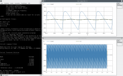
... just tested this python scripts to be able to work with ".wav" files as input/output:
GitHub - Ttl/spice-audio-tools
Works (note: you need a xspice enabled ngspice)! There are many other opensource tools to convert or view the wav files in/from any format you need ...
Have attached 2 wav files with 900mV pp ripple from my power supply simulation for your experiments. Note: european 50/100Hz !
Having fun with ngspice, Toni
P.S.: a small perl utility to generate SOA lines from only a few points ex log log scale from datasheet is in development. Maybe tomorrow ...
Attachments
Last edited:
Puuuh, first look of release 2.1.0 was nice ... but it's really buggy ... e.g. placed a component. couldn't select for remove ... suddenly could select and remove, leaves mask holes after removal ......
BTW, pcb-rnd is a fork of pcb which is more capable more actively developed. pcb has stagnated.
Sometimes less is more.
Of course it has nice features too:
- rotating text not only 90 degree
- more layer properties.
"pcb" is still actively maintained - in the last months more actively.
But I will keep "pcb-rnd" because it can read other pcb drawings and maybe I will use it if I ever need 4 layer pcb's.
Thx, Toni
Last edited:
Thx, yes, I have tested it, but I have so many schematic projects, pcbs and utilities for automating geda, pcb design I haven't the need to switch over.
If there is a KiCAD user feel free to post examples.
BR, Toni
BTW: how to select only a subset of data from a tran run for e.g. linearize v(output)?
If there is a KiCAD user feel free to post examples.
BR, Toni
BTW: how to select only a subset of data from a tran run for e.g. linearize v(output)?
ASTX LABS - SA2017 VMOS IXYS ngspice simulation test
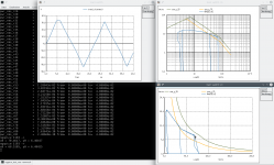
The ultimate combined simulation test ... That makes really fun")
For test I have changed several parameters - look for "v1_level" and "compose" and "alter" strings in the "combined .....ngspice"
It is really nice to get so much data from one stepping run without any mouse click...
Have fun, Toni
The ultimate combined simulation test ... That makes really fun
For test I have changed several parameters - look for "v1_level" and "compose" and "alter" strings in the "combined .....ngspice"
It is really nice to get so much data from one stepping run without any mouse click...
Have solved myself the question using a sample from our new member hvogt (ngspice developer!) - from ngspice forum....
BTW: how to select only a subset of data from a tran run for e.g. linearize v(output)?
Have fun, Toni
Attachments
Last edited:
ASTX LABS - SA2017 VMOS IXYS ngspice simulation test
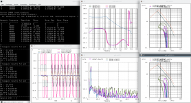
Attached an example for device stepping using different opamps.
The example shows how to use include files, save data for later evaluation.
Be warned that fft results of opamps are not very reliable!
To run the simulation you need ngspice 30 with 2 unofficial patches (developed by astx).
Hopefully the patches / functionality (included in the zip file) will find the way into the next ngspice release...
Have fun, Toni
Attachments
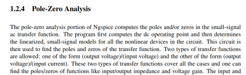
There is one feature of ngspice that intrigues me and, this is only a guess, might possibly intrigue Bob Cordell too. That is its "Pole Zero Analysis" whose description in the User Manual is excerpted below.
Is this feature actually implemented in the current release of ngspice? Is it stable, reliable, and more or less free of ridiculous oversimplifications? Bugs?
It would be VERY nice to have a way to accurately calculate "Right Half Plane Zeroes" and "Higher Order Poles" when developing the compensation strategy of an audio power amplifier. Has anyone done this using ngspice? Did it give you the right answer?
_
Attachments
Last edited:
I gather that nobody has tried pole zero analysis in ngspice and thus its bugginess / robustness is unknown.
Personally, I am happy to wait. I am comfortable letting somebody else be the pioneer who prepares test cases, uncovers bugs in ngspice, files bug reports & trouble tickets, and runs regression testing.
_
LTSPICE doesn't have pole zero analysis.
According to this version of the user manual, neither does PSPICE.
TI-TINA doesn't have pole zero analysis.
HSPICE from Synopsys does have pole zero analysis but the license fee is several hundred thousand dollars.
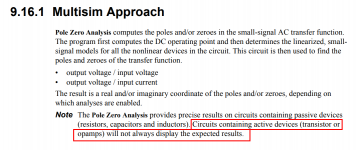
Multisim does offer pole zero analysis, but it employs some kind of computational approximations which don't give the right answer in the cases we care about (red highlighting in image below)
According to this version of the user manual, neither does PSPICE.
TI-TINA doesn't have pole zero analysis.
HSPICE from Synopsys does have pole zero analysis but the license fee is several hundred thousand dollars.
Multisim does offer pole zero analysis, but it employs some kind of computational approximations which don't give the right answer in the cases we care about (red highlighting in image below)
Personally, I am happy to wait. I am comfortable letting somebody else be the pioneer who prepares test cases, uncovers bugs in ngspice, files bug reports & trouble tickets, and runs regression testing.
_
Attachments
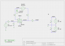
here are the reasults running ngspice using this netlist and "pz" afterwards ...
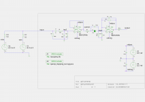
Schematic from above opamp circuit.
BR, Toni
Schematic from above opamp circuit.
BR, Toni
Code:
 toni@tnserver01:~/pcb/simulations/ngspice/opamp> cat gg.net
*
***** NE5532 Source: Texas Instruments NE5534
* [EMAIL="astx@aws-it.at"]astx@aws-it.at[/EMAIL]: modified NE5534 with fixed compensation cap
* NE5532 OPERATIONAL AMPLIFIER "MACROMODEL" SUBCIRCUIT
* CREATED USING NE5534 model from Texas InstrumentsAT 12:41
* (REV N/A)      SUPPLY VOLTAGE: +/-15V
* CONNECTIONS:   NON-INVERTING INPUT
*                | INVERTING INPUT
*                | | POSITIVE POWER SUPPLY
*                | | | NEGATIVE POWER SUPPLY
*                | | | | OUTPUT
*                | | | | |
.SUBCKT NE5532   1 2 3 4 5
*
C1   11 12 7.703E-12
C2    6  7 23.5p
DC    5 53 DX
DE   54  5 DX
DLP  90 91 DX
DLN  92 90 DX
DP    4  3 DX
EGND 99  0 POLY(2) (3,0) (4,0) 0 .5 .5
FB    7 99 POLY(5) VB VC VE VLP VLN 0 2.893E6 -3E6 3E6 3E6 -3E6
GA    6  0 11 12 1.382E-3
GCM   0  6 10 99 13.82E-9
IEE  10  4 DC 133.0E-6
HLIM 90  0 VLIM 1K
Q1   11  2 13 QX
Q2   12  1 14 QX
R2    6  9 100.0E3
RC1   3 11 723.3
RC2   3 12 723.3
RE1  13 10 329
RE2  14 10 329
REE  10 99 1.504E6
RO1   8  5 50
RO2   7 99 25
RP    3  4 7.757E3
VB    9  0 DC 0
VC    3 53 DC 2.700
VE   54  4 DC 2.700
VLIM  7  8 DC 0
VLP  91  0 DC 38
VLN   0 92 DC 38
.MODEL DX D(IS=800.0E-18)
.MODEL QX NPN(IS=800.0E-18 BF=132)
.ENDS
*==============  Begin SPICE netlist of main design ============
C6 railneg 0 100n
C3 0 railpos 100n
*.INCLUDE opamp_stepping_test.ngspice
X2 inp3 3 railpos railneg 4 ne5532
X1 inp2 outmid railpos railneg outmid ne5532
R9 input vmix 50
R7 input vein 50
V4 vmix 0 dc 0 ac 0
V1 vein 0 dc 0 ac 0
V3 0 railneg DC 14V
V2 railpos 0 DC 14V
C5 2 inp3 100n
C4 2 inp3 47u
R8 inp3 0 10k
C1 input 1 1u
R14 output 4 47
C8 3 4 15p
R12 4 3 1k
R10 3 0 270
R1 input 0 180k
R6 2 outmid 47
C2 0 inp2 680p
R3 inp2 0 47k
R2 inp2 1 560
.options savecurrents
.end
Code:
ngspice 2517 -> pz input 0 output 0 vol pz
Reducing trtol to 1 for xspice 'A' devices
Doing analysis at TEMP = 27.000000 and TNOM = 27.000000
Warning: Pole-zero iteration limit reached; giving up after 292 trials
Warning: Pole-zero iteration limit reached; giving up after 256 trials
No. of Data Rows : 1
ngspice 2518 -> print all
@c.x1.c1[i] = 0.0000000e+00,0.0000000e+00
...
@r14[i] = 0.0000000e+00,0.0000000e+00
pole(1) = -6.448271e+07,0.0000000e+00
pole(2) = -5.909002e+07,0.0000000e+00
pole(3) = -6.664565e+05,0.0000000e+00
pole(4) = -4.246934e+04,0.0000000e+00
pole(5) = -4.576797e+00,0.0000000e+00
pole(6) = -9.078086e-02,0.0000000e+00
pole(7) = 4.1096170e+04,0.0000000e+00
pole(8) = 9.3701938e+08,0.0000000e+00
zero(1) = -3.112961e+08,0.0000000e+00
zero(2) = 0.0000000e+00,0.0000000e+00
zero(3) = 0.0000000e+00,0.0000000e+00
zero(4) = 4.4597922e+02,0.0000000e+00
zero(5) = 1.7216954e+03,0.0000000e+00
zero(6) = 2.2142360e+10,0.0000000e+00
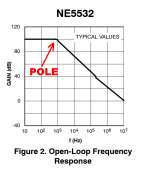
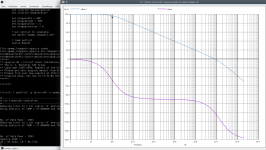
zero(7) = 2.2371969e+10,0.0000000e+00Attached is a figure from Fairchild / ON Semiconductor's datasheet for the NE5532. It shows a pole at about 0.9 kHz which is 5.6 kradians/sec.
The NGSPICE output seems not to include this pole. It does show pole #6 at 0.1 hertz (!!) which is, um, unexpected. Also unexpected are zeros 2 and 3 which are both at the origin, 0 hertz. Namely DC.
Good luck and best wishes to all ngspice users.
_
The NGSPICE output seems not to include this pole. It does show pole #6 at 0.1 hertz (!!) which is, um, unexpected. Also unexpected are zeros 2 and 3 which are both at the origin, 0 hertz. Namely DC.
Good luck and best wishes to all ngspice users.
_
Attachments
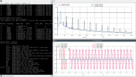
This is the ngspice calculated open loop gain using the tian method. And the "PZ" result data. Also nonsense?
BR, Toni
BR, Toni
Code:
ngspice 2550 -> pz input 0 output 0 vol pz
Reducing trtol to 1 for xspice 'A' devices
Doing analysis at TEMP = 27.000000 and TNOM = 27.000000

No. of Data Rows : 1
ngspice 2551 -> print all
pole(1) = -9.8374920e+21,0.00000000e+00
pole(2) = -2.1962622e+21,0.00000000e+00
pole(3) = -1.4621165e+21,0.00000000e+00
pole(4) = -3.1984562e+20,0.00000000e+00
pole(5) = -8.5750617e+19,0.00000000e+00
pole(6) = -3.8854029e+19,0.00000000e+00
pole(7) = -7.8806826e+18,0.00000000e+00
pole(8) = -2.0425105e+18,0.00000000e+00
pole(9) = -2.3921894e+17,0.00000000e+00
pole(10) = -1.1784836e+16,0.00000000e+00
pole(11) = -6.4100806e+15,0.00000000e+00
pole(12) = -2.2169509e+15,0.00000000e+00
pole(13) = -1.3116143e+14,0.00000000e+00
pole(14) = -5.8642989e+13,0.00000000e+00
pole(15) = -2.7689940e+12,0.00000000e+00
pole(16) = -5.5471852e+11,0.00000000e+00
pole(17) = -8.4198619e+07,0.00000000e+00
pole(18) = -2.8226182e+04,0.00000000e+00
pole(19) = 2.61629098e+12,0.00000000e+00
pole(20) = 9.95613872e+12,0.00000000e+00
pole(21) = 2.49126545e+13,0.00000000e+00
pole(22) = 4.52341785e+13,0.00000000e+00
pole(23) = 2.85517059e+14,0.00000000e+00
pole(24) = 7.70512294e+14,0.00000000e+00
pole(25) = 1.39993326e+15,0.00000000e+00
pole(26) = 2.02727949e+16,0.00000000e+00
pole(27) = 6.40211602e+16,0.00000000e+00
pole(28) = 1.55623497e+17,0.00000000e+00
pole(29) = 2.98666754e+17,0.00000000e+00
pole(30) = 9.43640219e+17,0.00000000e+00
pole(31) = 1.93026852e+18,0.00000000e+00
pole(32) = 5.27336751e+18,0.00000000e+00
pole(33) = 1.68749867e+19,0.00000000e+00
pole(34) = 5.84369781e+19,0.00000000e+00
pole(35) = 1.00515900e+20,0.00000000e+00
zero(1) = -1.4531505e+06,5.94125418e+06
zero(2) = -1.4531505e+06,-5.9412542e+06
Attachments
In fact the pz code base is old, not well maintained and buggy. If somebody has programming know-how and interest to improve that, you are welcome!
It then has to happen what is quoted below:
It then has to happen what is quoted below:
... be the pioneer who prepares test cases, uncovers bugs in ngspice, files bug reports & trouble tickets, and runs regression testing.
...
Hopefully the patches / functionality (included in the zip file) will find the way into the next ngspice release...
Thx goes to ngspice developers for implementing the patch into the current pre-master release to allow "linerarize" using a custom simulation time range!
It would be nice, if the other patch could be discussed too (avoid writing empty current vectors).
BR, Toni
It would be nice, if the other patch could be discussed too (avoid writing empty current vectors).
I am lost a bit. Where may I find that patch? Best would be to use the ngspice patch tracker at ngspice / Patches
Holger
- Home
- Design & Build
- Software Tools
- Installing and using ngspice - an opensource simulator