In a bid to teach myself about amplifier circuits, I wanted to simulate the Rotel RB850. My intent is to understand classic amplifier principles, not explore the detailed performance of the RB850.
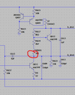
The schematic is available in the service manual, and it appears to be a near textbook class AB implementation, with differential input stage, current source for the bias chain, and paralleled output transistors, all driven off twin plus/minus power rails.
(link to service manual)
And...
It turns out that virtually none of the transistors in it have Spice models available.
The list is:
pnp 2sa1016
pnp 2sb631
npn 2sd600
npn 2sc1941
npn 2sd1047
pnp 2sb817
OTOH, I have (easily) found data sheets for them all.
Should I:
A) Look for equivalent devices that DO have Spice models?
B) Create my own "rough" Spice models using parameters from the Sheets
C) Simulate another amplifier?
BugBear
Last edited:
I would use models that are easily available and see where that gets you. Most circuits can be simulated very well from just a handful of generic parts (models). You will find using different models in most amplifier circuits makes very little difference to the result... and in fact in real life the same would apply in the majority of cases.
2N5551, 2N5401, MJE340, MJE350 and MJL21194 and MJL21193 would cover pretty much any audio amp.
2N5551, 2N5401, MJE340, MJE350 and MJL21194 and MJL21193 would cover pretty much any audio amp.
Thank you. I note that most of those transistors are not in "pick a new transistor" in my install of LTSpice XVII.I would use models that are easily available and see where that gets you. Most circuits can be simulated very well from just a handful of generic parts (models). You will find using different models in most amplifier circuits makes very little difference to the result... and in fact in real life the same would apply in the majority of cases.
2N5551, 2N5401, MJE340, MJE350 and MJL21194 and MJL21193 would cover pretty much any audio amp.
Do I need to install some "well known" upgrade/library?
EDIT;a wander round the install directories shows a "standard.bjt" file with a total of 62 models in it.
BugBear
Last edited:
Here is a model file (its just a txt document but because its around 300kb in size I'll have to zip it).
You need to do one of two things to use it. You can either give it a name (anything) and as long as you keep the file in the same folder as your .asc it will work. I called it discrete models.
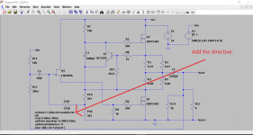
You need to add as .op command the instruction .include anything.txt or whatever name you used.
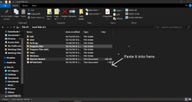
You can also (my preferred option) copy the file directly to the root of your C drive. Now you can call the file up from any .asc anywhere on your PC. Notice the file path now says .include C:\discrete models.txt
If you try and paste the file and Windows objects then open Notepad as admin (right click Notepad and select run as admin) and then browse for the text file and copy it. It should then paste with Notepad running under admin privileges.
To use any model simply right click the transistors type number on the .asc which will either be the default NPN, PNP etc or perhaps a model you are already using such as 2N3055. Having done that just enter the new model description exactly as it appears in the .txt file. For example Bob Cordell's 2N5401 would be 2N5401C
You need to do one of two things to use it. You can either give it a name (anything) and as long as you keep the file in the same folder as your .asc it will work. I called it discrete models.
You need to add as .op command the instruction .include anything.txt or whatever name you used.
You can also (my preferred option) copy the file directly to the root of your C drive. Now you can call the file up from any .asc anywhere on your PC. Notice the file path now says .include C:\discrete models.txt
If you try and paste the file and Windows objects then open Notepad as admin (right click Notepad and select run as admin) and then browse for the text file and copy it. It should then paste with Notepad running under admin privileges.
To use any model simply right click the transistors type number on the .asc which will either be the default NPN, PNP etc or perhaps a model you are already using such as 2N3055. Having done that just enter the new model description exactly as it appears in the .txt file. For example Bob Cordell's 2N5401 would be 2N5401C
Attachments
Wow - thank you very much.Here is a model file (its just a txt document but because its around 300kb in size I'll have to zip it).

BugBear
 if its working you have done it correctly, but as with most things LT related there are several ways to do the same thing.
So for me with the file named as discrete models the file either has to be in the same folder as the .asc's and simply linked to by adding .include discrete models.txt or, to save having zillions of copies of the model file if you have lots of folders with .asc's in them (because each folder would need its own copy) you just add it to the root of the C drive and link each .asc with the directive .include C:\discrete models.txt
You can add models (copy and paste) directly to the library files but the disadvantage of that is that the installation then becomes very customised around the PC its installed on. Having a separate model file makes it seconds work to use on any PC.
Well done
There is just one really simply drafting error and then it all works just fine.
I altered the way you entered the values (before I spotted the error) because I wasn't sure on how your method would work.
10k5 is entered as 10k5 or 10.5k or 10500.
A 1uF cap can be 1u or 1uF. Curiously LTspice calls 1 a 1 Farad cap and 1F a 1 Femto Farad. How confusing is that? 1 pico Farad would be 1p or 1pF.
Anyhow here we go... see if you can spot the error. You will need to tweak the bias setting resistor to get the current you want.
There is just one really simply drafting error
and then it all works just fine.I altered the way you entered the values (before I spotted the error) because I wasn't sure on how your method would work.
10k5 is entered as 10k5 or 10.5k or 10500.
A 1uF cap can be 1u or 1uF. Curiously LTspice calls 1 a 1 Farad cap and 1F a 1 Femto Farad. How confusing is that? 1 pico Farad would be 1p or 1pF.
Anyhow here we go... see if you can spot the error. You will need to tweak the bias setting resistor to get the current you want.
Attachments
Heh. Thanks for that. I entered the values the way LTspiceXVII appeared to be prompting me to.Well done
There is just one really simply drafting error
I altered the way you entered the values (before I spotted the error) because I wasn't sure on how your method would work.
10k5 is entered as 10k5 or 10.5k or 10500.
A 1uF cap can be 1u or 1uF. Curiously LTspice calls 1 a 1 Farad cap and 1F a 1 Femto Farad. How confusing is that? 1 pico Farad would be 1p or 1pF.
Anyhow here we go... see if you can spot the error. You will need to tweak the bias setting resistor to get the current you want.
I'll try to find my drafting error!
I've already discovered (whilst playing with sub-circuits trying to learn stuff) that circuits with heavy NFB behave in quite spectacular ways when they're wrong.
BugBear
You're welcome
It took me ages to figure out why making caps larger and larger suddenly 'failed'. For example 800,000uF works, 999,000uF works 1.1F (presumed Farad) didn't. Just one of its little peculiarities.
If you drawn an imaginary horizontal line through your diagram, the error is in the lower half
It took me ages to figure out why making caps larger and larger suddenly 'failed'. For example 800,000uF works, 999,000uF works 1.1F (presumed Farad) didn't. Just one of its little peculiarities.
If you drawn an imaginary horizontal line through your diagram, the error is in the lower half
In case you were wondering, the two "sense" resistors I added are used for measuring current (from the current sources).You're welcome
It took me ages to figure out why making caps larger and larger suddenly 'failed'. For example 800,000uF works, 999,000uF works 1.1F (presumed Farad) didn't. Just one of its little peculiarities.
If you drawn an imaginary horizontal line through your diagram, the error is in the lower half
Despite LTspice showing "click to measure current in this wire" when I hold the Alt key, clicking does NOT (in fact) do anything.
So I added very-small resistors to show currents.
BugBear
OK. You got me.
This means that either:
BugBear
- I've checked all the wiring (especially where wires cross without connecting). I re-drew the huge NFB loop using net labels. Much nicer.
- I've checked that all NPN transistors are drawn as NPN, and (in the new gloriousness) have npn models associated with them. (LTSpice doesn't check this )
- ditto for PNP
- I've checked that all capacitors have the values indicated on the schematic in the manual (the default units seems to the μF, so that 100V1 means a 100v, 1uF capacitor).
This means that either:
- I've missed it. Twice.
- it's some other kind of error
BugBear
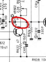
In that case it's wrong on their schematic!Here you go:
I was trying to find the fault by checking against their schematic.
BugBear
Attachments
Interesting.
Service manuals often do have errors unfortunately, usually voltages that are hopelessly incorrect. That transistor is the VAS or voltage amplification stage and is a fairly standard building block in most designs. Look at a few circuits and you'll see how similar they are.
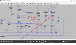
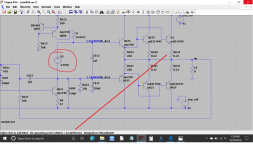
The basic amplifier (any common design) has the bias generator (which is Q613 on your design) located between the two bases of the driver transistors. So you can link out Q613 an run the amp with no bias, and equally you can substitute Q613 with a voltage source.
If you click on a part of the circuit you can attach the actual voltage present.
So here the bias voltage is approx. 2.3956 volts and that gives 42.58ma bias current. Now snip the transistor out and replace with a voltage source and we get the same result.
Service manuals often do have errors unfortunately, usually voltages that are hopelessly incorrect. That transistor is the VAS or voltage amplification stage and is a fairly standard building block in most designs. Look at a few circuits and you'll see how similar they are.
The basic amplifier (any common design) has the bias generator (which is Q613 on your design) located between the two bases of the driver transistors. So you can link out Q613 an run the amp with no bias, and equally you can substitute Q613 with a voltage source.
If you click on a part of the circuit you can attach the actual voltage present.
So here the bias voltage is approx. 2.3956 volts and that gives 42.58ma bias current. Now snip the transistor out and replace with a voltage source and we get the same result.
Attachments
...A 1uF cap can be 1u or 1uF. Curiously LTspice calls 1 a 1 Farad cap and 1F a 1 Femto Farad. ....
And "1M" is a milli-Ohm; you want 1Meg for a big resistor.
And note that you don't enter "Ohm". It's a resistor, what else would it be? By the same one-track logic, you don't enter "F", it's a cap, it's gotta be in F.
Leave off the Farad-F, remember that impossible values are perfectly possible to SPICE, and you may see that "f" is "femto". A femto-F is practically useless in real circuits (certainly at audio) but to SPICE it is a perfectly valid value.
SPICE "accepts" units basically by ignoring them; it knows what unit it will use as soon as it knows the part-type C R L V I....
Then we get to the "human convenience" prefixes. Original-recipe SPICE did not observe letter-case. "m" or "M" could be milli- or Mega-. The fact that the originators choose to default to milli- has caused untold confusion. (The acceptance of "Meg" appears to be a special-case in the text parser.)
_______________
Seconding Mooly's teaching to "use what you got". Tubes is tubes, transistors is transistors. Get the polarity (N or P) right. Try to find a similar-size device, not a peewee input to sim a monster output. (However as SPICE often does not enforce blow-up limits, I have run a 1W tube in a 100W power stage and got a general idea of what it would do with a transmitter tube.)
A teeny transistor in a power stage may fall short because the internal resistances are large. A monster transistor in an input stage may not have any simulated gain at very small currents. But like framing house windows: you need a 2x4, you ran out, 2x8 fits and you have some, use the somewhat oversize stick.
So I added very-small resistors to show currents.
I've found sense resistors unnecessary to monitor CCS outputs because if you hover over the collector pin of the CCS transistor you'll get an icon looking somewhat like a black owl (or maybe cat?) with a circle underneath it. Left clicking this will give you the collector current. It works for all transistor terminals.
- Home
- Design & Build
- Software Tools
- Simulating Rotel RB850 in LTSpice?