Hi everybody,
Christian here hope you are all doing well, asking in regards to two questions and any help on either will really genuinely be appreciated.
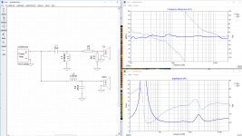
I'm starting to break down here a bit, I am currently trying to make a nice high-end set of bookshelf speakers and we all know the crossover is so essential to having that final great sound. I've currently done some messing around and just for now I have come up with this (see crossover1 photo) yes it isn't perfect and may require a notch at 700hz etc I understand...
(NOTE HOW BOTH DRIVERS ARE CONNECTED WITH +, TRYING TO ACHIEVE THE "IDEAL" LWR 2 CROSSOVER.)
First of all regarding crossover software, I personally use XSim. Does the software assume that EG a 2-way bookshelf speaker that the acoustic sources of energy (lets say the dustcap on a woofer and top of dome on tweeter) are in alignment to start with when in reality on a flat 90 degree baffle the woofer is behind the tweeter by that little bit? Would this not make sense to design the speaker with a delay behind how much the woofer is behind the tweeter on your 99 out of 100 speakers? And let’s say we are to adjust offset by let’s say woofer 1 inch in front would this program assume the acoustic source (dust cap) is actually one inch in front of the tweeter when in reality is actually near perfect aligned? So is it telling you what the drivers "physically aligned" is or is it plus the 1 inch you added which would make it one inch in front of the tweeter? But how come when in practice it actually works as we want it to, are the programs designed in mind with the standard that the woofer is a set distance behind the tweeter ?
This then leads into my second and just as important question to me.
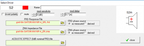
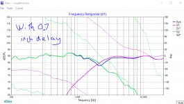
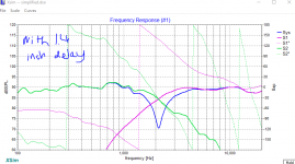
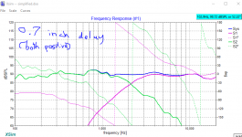
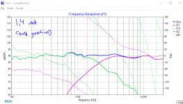
In photo crossover2, we can see that I've adjusted the offset of the woofer by 0.7 inches in front. If I am to invert the tweeter (see crossover 3) we get that response. with a shallow dip at the crossover frequency. However, if I then go ahead and adjust that delay to 1.4 inches, and reverse the polarity on the tweeter (refer to photo crossover4) we get a much deeper, sharper dip at the crossover frequency. Is this not showing much, much better agreement with drivers when the woofer is 1.4 inch in front? am I missing something here guys? is the shallow "null" with 0.7 inch delay with a driver reversed polarity not giving optimal phase results?
Thanks guys for taking your time to read this and hope to hear from some of you!!
Christian here hope you are all doing well, asking in regards to two questions and any help on either will really genuinely be appreciated.
I'm starting to break down here a bit, I am currently trying to make a nice high-end set of bookshelf speakers and we all know the crossover is so essential to having that final great sound. I've currently done some messing around and just for now I have come up with this (see crossover1 photo) yes it isn't perfect and may require a notch at 700hz etc I understand...
(NOTE HOW BOTH DRIVERS ARE CONNECTED WITH +, TRYING TO ACHIEVE THE "IDEAL" LWR 2 CROSSOVER.)
First of all regarding crossover software, I personally use XSim. Does the software assume that EG a 2-way bookshelf speaker that the acoustic sources of energy (lets say the dustcap on a woofer and top of dome on tweeter) are in alignment to start with when in reality on a flat 90 degree baffle the woofer is behind the tweeter by that little bit? Would this not make sense to design the speaker with a delay behind how much the woofer is behind the tweeter on your 99 out of 100 speakers? And let’s say we are to adjust offset by let’s say woofer 1 inch in front would this program assume the acoustic source (dust cap) is actually one inch in front of the tweeter when in reality is actually near perfect aligned? So is it telling you what the drivers "physically aligned" is or is it plus the 1 inch you added which would make it one inch in front of the tweeter? But how come when in practice it actually works as we want it to, are the programs designed in mind with the standard that the woofer is a set distance behind the tweeter ?
This then leads into my second and just as important question to me.
In photo crossover2, we can see that I've adjusted the offset of the woofer by 0.7 inches in front. If I am to invert the tweeter (see crossover 3) we get that response. with a shallow dip at the crossover frequency. However, if I then go ahead and adjust that delay to 1.4 inches, and reverse the polarity on the tweeter (refer to photo crossover4) we get a much deeper, sharper dip at the crossover frequency. Is this not showing much, much better agreement with drivers when the woofer is 1.4 inch in front? am I missing something here guys? is the shallow "null" with 0.7 inch delay with a driver reversed polarity not giving optimal phase results?
Thanks guys for taking your time to read this and hope to hear from some of you!!
Attachments

Great stuff with simulators that take in acustical effects of off-set and dust caps. I am guessing that the dip variation is probably caused by the phase difference between the drivers themselves (not the total phase). I read a cowboy-trick somewhere, that you should be able to get away with flushmounting tweeter and bass by adding an extra pole in the tweeter crossover. That is 2. order filter for bas and 3.rd order for tweeter. I haven't tried it myself but it sounds plausible.
Anyway, the acoustic of any listening room is quite forgiving, and I am quite shure that the small dip at 0,7" offset is not audible, and not even measureable more than 3 feet away from the frontbaffle.
Anyway, the acoustic of any listening room is quite forgiving, and I am quite shure that the small dip at 0,7" offset is not audible, and not even measureable more than 3 feet away from the frontbaffle.
There is no need to make guesses about where the acoustic center may or may not lie on the driver diaphragm, etc. Instead, make some measurements and determine exactly how far apart the acoustic centers are for your particular set of drivers in the particular baffle mounting that you will be using. This means you need to build the loudspeaker FIRST, then measure, then design the crossover. When you know the acoustic center offset you can include it in the model of the system, e.g. in Xsim or whatever crossover modeling+design package you are using.
You can measure the acoustic offset using the interference between the output from two drivers and a program that will let you fitting the offset. There is a good explanation of this technique written by Jeff Bagby called "How To Use Passive Crossover Designer To Find The Relative Acoustic Offset". Just google it. Not sure if Xsim has this functionality or not.
You can measure the acoustic offset using the interference between the output from two drivers and a program that will let you fitting the offset. There is a good explanation of this technique written by Jeff Bagby called "How To Use Passive Crossover Designer To Find The Relative Acoustic Offset". Just google it. Not sure if Xsim has this functionality or not.
Last edited:
The delay is differential (i.e., apply to only one driver -- in most cases, add delay to the tweeter, moving it away from the mic). If you know where the pole pieces of the driver magnets are, those aren't usually terrible guesses of where you can estimate the positions to be if you don't have measurement gear.
That bump near 700Hz will probably be minor (and possibly nonexistent) compared to what baffle diffraction will do (Jeff Bagby and some others have software to estimate that). If you do measure (advisable), try to do it AFTER you make the baffle/box so you can measure the drivers on the baffle and box which will include those effects. Don't try to get too detailed unless you have real on-baffle measurements of your actual drivers -- reality in speaker design can unfortunately be a b**ch!")
That bump near 700Hz will probably be minor (and possibly nonexistent) compared to what baffle diffraction will do (Jeff Bagby and some others have software to estimate that). If you do measure (advisable), try to do it AFTER you make the baffle/box so you can measure the drivers on the baffle and box which will include those effects. Don't try to get too detailed unless you have real on-baffle measurements of your actual drivers -- reality in speaker design can unfortunately be a b**ch!
Last edited:
So when we build the loudspeaker and in real life it is offset by eg 18mm and we then measure that speaker at 1M does that then mean when we go to design the crossover we add that offset into the software or keep it at 0?
That depends on your measurement setup. Some systems (like Omnimic, I know the guy that designed it) don't take time of flight into account in the phase response -- Jeff Bagby has a writeup of how to get delay acccurate measurements with that setup http://techtalk.parts-express.com/filedata/fetch?id=1149302 -- the same method works with XSim, too. REW, if you get the time lock working, and some other systems can take time of flight delay into account in the actual measurements so you could skip those steps.
[a future version of Omnimic, "version 3" hardware, should be available at some time in the future, and will also be able to include delay in single measurements as well as reference 2.83V drive level for true sensitivity]
Last edited:
Standard (inexpensive) gear with semi-dual channel connection and measurement software in dual channel mode is able to measure timing/phase differences of non-minimum phase and non-flat radiators e.g. horns to all directions in 3D.
Capability to measure timing/phase differences is basic requirement to produce valid measurement data for crossover simulation which calculates and shows also off-axis, power and DI responses of multi-way speaker.
Summing method with tree single channel measurements to one direction works to that direction, but other directions and non minimum-phase radiators are not so sure and may need lots of extra work to get covered.
An externally hosted image should be here but it was not working when we last tested it.
Capability to measure timing/phase differences is basic requirement to produce valid measurement data for crossover simulation which calculates and shows also off-axis, power and DI responses of multi-way speaker.
Summing method with tree single channel measurements to one direction works to that direction, but other directions and non minimum-phase radiators are not so sure and may need lots of extra work to get covered.
[a future version of Omnimic, "version 3" hardware, should be available at some time in the future, and will also be able to include delay in single measurements as well as reference 2.83V drive level for true sensitivity]
This is quite an old thread, but I still cannot find information on this Omnimic hardware version 3...
Would someone know more about availability ?
Dominique
Any calibrated mic can be used with REW software to get the measurement you need. No need to get OmniMic. Crossspectrum Labs sells third party calibrated microphones for a very reasonable price (about $20 more than mic costs). MiniDSP UMIK-1 USB mic is very good. Eliminates need for a mic preamp with phantom 48v supply.
REW - Room EQ Wizard Room Acoustics Software
Cross·Spectrum - Calibrated MiniDSP UMIK-1 Microphones for Sale
As far as measuring exactly where the acoustic centers are: set up speaker with drivers mounted in baffle. Mount microphone and take 3 sweeps: tweeter only, woofer only, and both woofer and tweeter (this is the interferogram) Do this without physically touching speaker cabinet or mic. Import the measurement into the software Xsim or PCD. Adjust delay on one driver forward or backward until the simulated combined signal matches the measured combo exactly. It’s an acoustic interferogram so accurate to the mm or better. That’s basically what Jeff Bagby’s article will tell you. Once you have this, you know that the simulation of the XO will give you a perfect result because it accounts for the baffle geometry and the acoustic offset.
Last edited:
A question. I recently replaced the xovers in some book shelves with a dsp so I could biamp them. Feeding them with a step response and recording, thru mic, into a daw I adjusted the tweeter delay till the I got the best acoustic step. Only took fractions of a msec.
Was it a waste of time? Is a flat freq response more important?
Was it a waste of time? Is a flat freq response more important?
If you are biamping with DSP in a 2 way bookshelf, and you are concerned about timing, it does make an audible difference on percussion instruments to have as close to a transient perfect response as possible. Try the Harsch XO in your DSP. You won’t go back to LR.
S. Harsch XO
S. Harsch XO
I think my situation is a little more complicated, unfortunately.
Biamping a 2-way but strange x-over output, please help.
I have tried to copy the original xover response and have gotten fairly close, but it wasn't straight forward, the LF part took 3 eq sections. The speaker measures fairly flat ( I don't have the best test set up but the 2 speakers measure fairly close but are audibly not the same Freq response again there close. )
So now I'm thinking to tweak the step response with some delay, it seems to be working.
Thank you!
I have quite a large system:
Atelier estival a Winterscheid – Une passion audiophile
(Sorry, in French, but the illustrations speak by themselves).
I suppose the position of the microphone for the 3 measurements matters...
Dominique
I have quite a large system:
Atelier estival a Winterscheid – Une passion audiophile
(Sorry, in French, but the illustrations speak by themselves).
I suppose the position of the microphone for the 3 measurements matters...
Dominique
Any calibrated mic can be used with REW software to get the measurement you need. No need to get OmniMic. Crossspectrum Labs sells third party calibrated microphones for a very reasonable price (about $20 more than mic costs). MiniDSP UMIK-1 USB mic is very good. Eliminates need for a mic preamp with phantom 48v supply.
REW - Room EQ Wizard Room Acoustics Software
Cross·Spectrum - Calibrated MiniDSP UMIK-1 Microphones for Sale
As far as measuring exactly where the acoustic centers are: set up speaker with drivers mounted in baffle. Mount microphone and take 3 sweeps: tweeter only, woofer only, and both woofer and tweeter (this is the interferogram) Do this without physically touching speaker cabinet or mic. Import the measurement into the software Xsim or PCD. Adjust delay on one driver forward or backward until the simulated combined signal matches the measured combo exactly. It’s an acoustic interferogram so accurate to the mm or better. That’s basically what Jeff Bagby’s article will tell you. Once you have this, you know that the simulation of the XO will give you a perfect result because it accounts for the baffle geometry and the acoustic offset.
Right here: Dayton Audio OmniMic V2 Acoustic Measurement SystemThis is quite an old thread, but I still cannot find information on this Omnimic hardware version 3...
Would someone know more about availability ?
Dominique
I've had one for a year or two, and my only complaint is that the supplied USB cable is kind of short. I bought a USB3 16ft cable and it works great.
Mike
With non-coincident multiway systems there will always be some discrepancy between acoustic centers in 3D. The importance of this is highest with mid-tweeter xo, because of typical frequency/wavelength.
The cost common guide is to align voice coils, which is actually nonsense. But it comes from the PA speaker world where compression drivers and deep horns are widely used.
For typical hifi speakers with dome tweeters often in waveguides the physical offset is minimal, but still important. The location of acoustic centers is actually in front of the cone or dome! Here is an article about where it is discussed
https://pdfs.semanticscholar.org/2da5/e847af0ff7c5759506be4ac89d466703a88f.pdf
From this we may conclude that—at low frequencies (kR 0.4) — the acoustic center for a loudspeaker lies about 0–0.5R in front of the loudspeaker, where R is the radius in the case of a spherical cabinet, or some other dimensional measure of the cabinet. At higher frequencies the acoustic center shifts further away from the loudspeaker. For example, between kR¼1 (660 Hz) and kR¼2 (1.32 kHz) q is about 5 dB (see Fig. 9), corresponding to D ¼ 3.4R ¼ 280 mm [using Eq. (31)].
For hifi speakers and modern desing software that info is of crucial importance and best derived from impulse response of standardized measurements.
- Status
- This old topic is closed. If you want to reopen this topic, contact a moderator using the "Report Post" button.
- Home
- Design & Build
- Software Tools
- Time delay and phase in crossovers