Exactly! That is pretty much the set-up that I had been think...
I had a think myself and maybe have a tidier idea than the Klippel mechanics.
Kind of a cantilever version of the Weinriech setup.
Speaker is mounted on on a post.
Version 1 - a strut from the bottom of the post, pivoted so it can rotate around the post, a tie wire from the top of the post to hold the strut out at radius.
This provides azimuth control with minimal structure to disturb the sound field.
Can be easily automated to step the azimuth for version 2.
The end of the strut has a horizontal pivot for a quarter-circular cantilever arm that sweeps out the polar co-ordinate, small mike on the end.
The arm could be carbon fibre, thin, not heavy, minimal disturbance but still accurate placement.
So for on-axis measurement the strut is to the side at 90, the arm is horizontal, around the equator.
For vertical polars the arm is rotated up and down, easy and cheap to automate for V3.
This provides true spherical coordinate measurements, which simplifies the maths.
Make sense?
Best wishes
David
I note that the Klippel system is not $20,00 as Earl claimed but nearer $50,000 - just for hardware.
Software is $60,000, presumably they consider it not an easy problem.
If you commercialize I definitely want royalties
")
Last edited:
The Legendre polynomials Lgnd(x) are an orthogonal set defined between +1 and -1 along x. Fitting in x is best done on an equally spaced set of points along x. But to get into the spherical coordinate theta we must set x = cos(theta). Equal spacing along x is not equal spacing in theta. My spacing somewhat corrects that situation, but not entirely - it is still better than equal spacing. In reality equal spacing in theta works just about as well, but with maybe a few more points required for comparable accuracy.
...spherical coordinate theta we must set x = cos(theta)...
You use theta for the azimuth? For spherical coordinates I remember most of the physics literature uses phi for azimuth and theta as polar, which is inconsistent with many maths books, so I just want be sure I have it clear.
If we want equal cos(theta) then wouldn't that imply symmetrical intervals for the back and front?
That's intuitively unreasonable, we care more about the front, but I can't see how the mathematics will play out.
Similarly, I have looked at Klippel's scanner presentations and the illustrations show a cylindrical scan - this seems sub-optimal, wouldn't a spherical scan with fewer azimuth steps near the poles be more efficient?
But promotional material probably doesn't have the most careful illustrations, some of the pictures of spherical harmonics look faulty too.
Best wishes
David
Best wishes
David
The math usually assumes that the "north" pole is along the drivers axis, i.e. tilted towards the axis of symmetry (see Morse.) Yes, the cos(theta) does imply a finer resolution both forward and backwards, but backwards was clearly not of as much interest as forwards so I made it lessor resolution in the back. One could completely exclude the back without too much loss of information.
I had a think myself and maybe have a tidier idea than the Klippel mechanics.
Kind of a cantilever version of the Weinriech setup.
Speaker is mounted on on a post.
Version 1 - a strut from the bottom of the post, pivoted so it can rotate around the post, a tie wire from the top of the post to hold the strut out at radius.
This provides azimuth control with minimal structure to disturb the sound field.
Can be easily automated to step the azimuth for version 2.
The end of the strut has a horizontal pivot for a quarter-circular cantilever arm that sweeps out the polar co-ordinate, small mike on the end.
The arm could be carbon fibre, thin, not heavy, minimal disturbance but still accurate placement.
So for on-axis measurement the strut is to the side at 90, the arm is horizontal, around the equator.
For vertical polars the arm is rotated up and down, easy and cheap to automate for V3.
This provides true spherical coordinate measurements, which simplifies the maths.
Make sense?
I like the simplicity, but I'm not sure I'm picturing it correctly. I sketched how I saw the description (the one on the left). Clarifications are welcome.
The one on the right is one of my early ideas for the scanner hardware.
I note that the Klippel system is not $20,00 as Earl claimed but nearer $50,000 - just for hardware.
Software is $60,000, presumably they consider it not an easy problem.
If you commercialize I definitely want royalties
If I commercialize, you deserve royalties.
The first article I read about the NFS pointed out that it's a fifth of the starting price for a decent anechoic chamber, so it's a value priced system... like a used Rolls Royce.
...I have looked at Klippel's scanner presentations and the illustrations show a cylindrical scan - this seems sub-optimal...
My assumption is that they chose a cylindrical scanning surface so that the hardware would be easier to build and be more portable.
One could completely exclude the back without too much loss of information.
That sounds like it could then be worth also perusing a variation of this device that can measure a raw driver in a baffle. I recall you had mentioned something along the lines of using your measurement technique for drivers in a baffle in the other thread.
Attachments
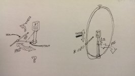
I sketched how I saw the description (the one on the left). Clarifications are welcome...
Almost, the strut and tie is correct
Now put the strut out to the side of the speaker.
On the end of the strut is a pivot and arm to scan in theta
The arm is a quarter circle that follows the equator to the front of the speaker.
The mike is perpendicular at the end of the arm, pointed at the speaker.
The mike could be manually moved in and out, to do a 2 surface scan.
That makes the mike mount very small for minimal disturbance, and one simple adjustment when necessary.
Picture later if this is not clear.
The rationale is that there is minimum structure and simple pivots, much cheaper and easier to automate than linear slides.
The Klippel mechanics seem quite clumsy, to be honest.
Best wishes
David
Last edited:
The math usually assumes that the "north" pole is ...the drivers axis
Thanks, that clarifies it.
The Klippel scanner illustrations have a vertical axis so I just used the same.
But your assumption makes more sense for an axisymmetrical driver.
My own speakers are not axisymmetric, perhaps that unconsciously influenced me too.
Best wishes
David.
Almost, the strut and tie is correct
Now put the strut out to the side of the speaker.
On the end of the strut is a pivot and arm to scan in theta
The arm is a quarter circle that follows the equator to the front of the speaker.
The mike is perpendicular at the end of the arm, pointed at the speaker.
The mike could be manually moved in and out, to do a 2 surface scan.
That makes the mike mount very small for minimal disturbance, and one simple adjustment when necessary.
Picture later if this is not clear.
The rationale is that there is minimum structure and simple pivots, much cheaper and easier to automate than linear slides.
The Klippel mechanics seem quite clumsy, to be honest.
Best wishes
David
Ahh, I think I've got it now. See attached (I didn't sketch the pivot for theta very well, but it's at the side of the speaker). I like the simplicity of it, certainly preferable to trying to do something like Klippel's Z axis.
I'm thinking the length of the microphone mount (D1 in the sketch) can assist in reducing the acoustic disturbance; with enough distance a long enough impulse window can be had to remove any reflections from the hardware but still provide enough resolution to provide detail down to around 1kHz or lower... dimensions depending, of course. Making those dimensions favorable to a long IR window could easily make the whole thing awkwardly large. I'm supposing that a two layer scan with field separation would help even more, we just have to get to that point.
Attachments
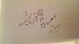
...See attached (I didn't sketch the pivot for theta very well, but it's at the side of the speaker). I like the simplicity of it
Thank you, I think it's a pretty neat solution, if I may say so myself.
...impulse window can be had to remove any reflections from the hardware...a two layer scan with field separation would help even more...
It should be possible to have cleaner IR than the Klippel structure and still keep the size reasonable.
Even without 2 layer scan the results should be as accurate as any other technique short of an anechoic chamber.
we just have to...
I see the problem in 3 steps.
First - 1-d horizontal scan with Legendre polynomial solution, essentially what Earl's PolarMap does. Room reflections are removed by time window.
Second - Full spherical scan with spherical harmonic solution, as Earl notes in the PolarMap doco, this is rather more difficult.
Third - 2 layer scan to remove room reflections, this requires the radial expansion in Hankel functions (or equivalently Bessel).
I still don't have an intuitive feel for the third step partly because I don't know how Klippel combines time window and 2 layer measurements.
Does Klippel have a manual for their scanner?
@Earl, do you have any ideas about this?
Best wishes
David
I will have a look at the Klippel patents and see what I can learn.
Last edited:
@Aaron, I looked at the Klippel patent, fortunately it covers exactly the part I don't understand, the 2 layer reflection extraction process... unfortunately it's not very simple.
Probably why that module of software is ~ $24,000.
I think I need to find a copy of "Fourier Acoustics" by Williams.
Best wishes
David
Probably why that module of software is ~ $24,000.
I think I need to find a copy of "Fourier Acoustics" by Williams.
Best wishes
David
I see the problem in 3 steps.
First - 1-d horizontal scan with Legendre polynomial solution, essentially what Earl's PolarMap does. Room reflections are removed by time window.
Second - Full spherical scan with spherical harmonic solution, as Earl notes in the PolarMap doco, this is rather more difficult.
Third - 2 layer scan to remove room reflections, this requires the radial expansion in Hankel functions (or equivalently Bessel).
That sounds like a very logical way to go about this. And honestly, even if it doesn't progress past step one or two, this is a huge step forward in DIY measurement methods.
...I don't know how Klippel combines time window and 2 layer measurements.
Do you think it would be possible to do that in a similar way to combining ground plane and time window measurements? In other words, take the measurement set and process the low and high frequencies separately, then recombine the results after.
@Aaron, I looked at the Klippel patent, fortunately it covers exactly the part I don't understand, the 2 layer reflection extraction process... unfortunately it's not very simple.
Probably why that module of software is ~ $24,000.
I think I need to find a copy of "Fourier Acoustics" by Williams.
I have to say though, even though it's not very simple, I find it encouraging that there's actually details. I mean, in Weinreich's paper, all it really says on the topic is "Having obtained the spherical harmonic expansion of the acoustic field on each sphere, it is a simple matter (knowing the radii, the frequency, and the speed of sound) to obtain the coefficients of the incoming and outgoing waves."
Last edited:
That sounds like a very logical way...
It is the natural way the mathematical steps follow.
It wasn't until after I worked this out that I belatedly remembered that Klippel sells the software in modules and they have parts one and two included with the scanner but part three is separate and extra.
So they think it's a natural subdivision too.
Do you think it would be possible to do that in a similar way...
Not sure yet. The patent application is >Here< and it's not an easy read.
Our first two steps are fairly classic bits of mathematics but this last step is rather specific to this problem, not the sort of stuff that maths classes cover and outside my area.
So I don't really understand it yet.
But luckily my university library has a copy of the primary reference, "Fourier Acoustics" by Earl Williams (what is up with acoustics and people called 'Earl'?).
I will try to study it in the next few days.
Best wishes
David
Last edited:
... in Weinreich's paper, all it really says on the topic is "...obtained the spherical harmonic expansion of the acoustic field on each sphere, it is a simple matter...to obtain the coefficients..."
OK, I think I have the idea on how to do this. Basically this allows us to calculate the room echoes.
The Klippel patent is for a further extension of this, to provide a more accurate calculation.
It includes the echoes off the speaker of the room echoes.
It can be wish-list step 4, it's above my pay scale
A combination of time windowed and basic 2 layer should still be a substantial improvement on current methods.
The limitation is that the speaker dimensions need to be small in comparison with the measurement space.
So for small to medium speakers we're fine in a normal room.
Klippel claim that they can measure a bulky, pro-audio speaker in a small room but it's a fairly rare requirement.
I have tallish speakers at 1.8 m so I would appreciate the convenience to measure them anywhere but realistically, such speakers are usually in substantial rooms.
Best wishes
David
I finally have a new monitor and was able to have a better look at the Klippel patent.
It's pretty clever - they use the measurements after the time window, that are normally discarded.
But these are exactly the room reflections that we need to worry about at low frequencies.
So they process this information to improve the 2 layer data extraction.
This also partly explains their choice of a cylindrical scan, they can dynamically choose the microphone radial distance for the second scan in response to the data from the first layer scan.
That's impressive - and I have no inclination to try to match it probably took a few man-years of work for Klippel and his PhD level staff.
I still think time window and simple 2 layer extraction looks fine, library tomorrow should explain more.
Best wishes
David
It's pretty clever - they use the measurements after the time window, that are normally discarded.
But these are exactly the room reflections that we need to worry about at low frequencies.
So they process this information to improve the 2 layer data extraction.
This also partly explains their choice of a cylindrical scan, they can dynamically choose the microphone radial distance for the second scan in response to the data from the first layer scan.
That's impressive - and I have no inclination to try to match it
probably took a few man-years of work for Klippel and his PhD level staff.I still think time window and simple 2 layer extraction looks fine, library tomorrow should explain more.
Best wishes
David
I see the problem in 3 steps.
First - 1-d horizontal scan with Legendre polynomial solution, essentially what Earl's PolarMap does. Room reflections are removed by time window.
Second - Full spherical scan with spherical harmonic solution, as Earl notes in the PolarMap doco, this is rather more difficult.
Third - 2 layer scan to remove room reflections, this requires the radial expansion in Hankel functions (or equivalently Bessel).
I still don't have an intuitive feel for the third step partly because I don't know how Klippel combines time window and 2 layer measurements.
Does Klippel have a manual for their scanner?
@Earl, do you have any ideas about this?
Best wishes
David
I will have a look at the Klippel patents and see what I can learn.
Been gone for a week, just now back.
Yes, this seems a logical way to proceed.
My PolarMap also use the radial Hankel functions as they are required in every case when adding the angular radiation modes back together to get the far field radiation pattern.
I am surprised that Klippel has filed a patent as this is all old stuff. All he did was to automate it. I am not sure that is patentable - maybe some details get through, that's usually the case. I even have a patent on similar techniques.
That's what I do nowDo you think it would be possible to do that in a similar way to combining ground plane and time window measurements? In other words, take the measurement set and process the low and high frequencies separately, then recombine the results after.
I have to say though, even though it's not very simple, I find it encouraging that there's actually details. I mean, in Weinreich's paper, all it really says on the topic is "Having obtained the spherical harmonic expansion of the acoustic field on each sphere, it is a simple matter (knowing the radii, the frequency, and the speed of sound) to obtain the coefficients of the incoming and outgoing waves."
I don't think that it really is that complicated once you understand how sound is radiated in spherical coordinates. Its simply two equations in two unknowns at ever frequency. The two unknowns are the coefficients of the real and imaginary parts of the wave from which one can calculate the outgoing and incoming contributions.
The real problem in all this is something that has not even been touched on and that is that the inverse problem is singular in all the modes > 0. I am curious how Klippel handles this. Initially (I actually tried this some 20+ years ago) I gave up because of the singularities. But then I found a way around them and it all fell in place.
(what is up with acoustics and people called 'Earl'?).
Best wishes
David
And even more coincidentally, Earl Williams and I were both at Penn State working on our PhDs at the same time.
It's pretty clever - they use the measurements after the time window, that are normally discarded.
But these are exactly the room reflections that we need to worry about at low frequencies.
So they process this information to improve the 2 layer data extraction.
This also partly explains their choice of a cylindrical scan, they can dynamically choose the microphone radial distance for the second scan in response to the data from the first layer scan.
That's impressive - and I have no inclination to try to match it
I still think time window and simple 2 layer extraction looks fine, library tomorrow should explain more.
Best wishes
David
But Weinreich did not use a time window either, so this is not a new "improvement".
The math looks daunting at first, but once you get through it, it all falls together. I can do the math, that's not an issue, its doing the hardware and software that I am not really equipped to do. My system is a simple 2x4 assembled stand with a rotating top - cost about $10. Automation is way beyond my capabilities.
I have Earl Williams book, what section is referenced? Does Klippel reference my patent? If not then that could be a problem for him.
What I would like to do to further this technique is to do a circular source in an infinite baffle. I believe that this technique could reconstruct the cone motion fairly easily with reasonable accuracy. This is what I tried decades ago and failed because of the singularities, but today, I know how to do it, with one exception. That is that an infinite baffle is impossible to create. But perhaps the two radius solutions could extract the radiating field from the baffles edge diffraction, which otherwise could be an issue.
..Does Klippel reference my patent? If not then that could be a problem for him.
Your patent is cited as prior art, by the examiner.
More detailed response soon.
Best wishes
David
- Home
- Design & Build
- Software Tools
- Klippel Near Field Scanner on a Shoestring