Bravo! Thanks for a great program and all your work. I had previously seen this thread and forgotten about it, but stumbled on it again and decided to try it out. After a couple of test projects I imported a system response .frd from a crossover I had created by hand and used it as the target. XMachina created a crossover that had the same number of parts in a lot less time. It's great to have XMachina as an option to hand crafting crossovers.
The only thing I noticed was that XMachina is suffering from every software developer's lament: keeping the documentation up to date with the program. You've added several nice additional features (e.g. Follow the woofer TOOL, (Delta) Average, Automatic Curve Reader, etc.) that I didn't see in the pdf. As a former developer I realize what a pain keeping the documentation up to date can be. The joy is writing the code and seeing it work.
Thanks again for this tool.")
The only thing I noticed was that XMachina is suffering from every software developer's lament: keeping the documentation up to date with the program. You've added several nice additional features (e.g. Follow the woofer TOOL, (Delta) Average, Automatic Curve Reader, etc.) that I didn't see in the pdf. As a former developer I realize what a pain keeping the documentation up to date can be. The joy is writing the code and seeing it work.
Thanks again for this tool.
1) Impedance phase equalization option introduced. (dBspl phase linearisation has also been implemented but it needs further testing and modifications so for now it's inactive).
How is this coming?
Needs rethinking and probably a change of approach. I will come back to this sometime (for now it's on hold)
Bravo! Thanks for a great program and all your work. I had previously seen this thread and forgotten about it, but stumbled on it again and decided to try it out. After a couple of test projects I imported a system response .frd from a crossover I had created by hand and used it as the target. XMachina created a crossover that had the same number of parts in a lot less time. It's great to have XMachina as an option to hand crafting crossovers.
The only thing I noticed was that XMachina is suffering from every software developer's lament: keeping the documentation up to date with the program. You've added several nice additional features (e.g. Follow the woofer TOOL, (Delta) Average, Automatic Curve Reader, etc.) that I didn't see in the pdf. As a former developer I realize what a pain keeping the documentation up to date can be. The joy is writing the code and seeing it work.
Thanks again for this tool.
Thank you for your comment. I usually try to give a short description of the new functionalities together with information about the release of new version, but thats true that the .pdf needs to be updated. The problem is that I can spend only little time on XMachina development, usually late evenings, so the documentation updates are set on lower priority. And I'm really surprised that you have noticed a feature of the latest version that I haven't described yet!
New version of XMachina: [1191023].
1) important bug fix for impedance characteristic calculation.
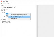
2) Automatic Curve Reader feature in "Load characteristic from picture" window.
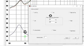
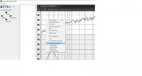
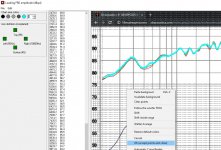
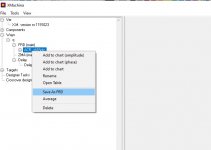
Make a screenshot of the characteristic. Right click on the FRD (or ZMA) node and choose „Load from picture” from the menu. Paste your picture with the characteristic to digitize. It can be strongly zoomed, no need to worry that it won’t fit into the window (it has scrollbars). Click on the chart and enter frequency and dBspl for the clicked point. Do the same for another point on the chart. This is done to establish translation from pixels X-Y coordinates into frequency-dBspl domain. Right click on the picture an choose “Automatic Curve Reader” from the menu. Click on the curve you want to digitize to get it’s color and see the result. If the picture is noisy or there are more curves/objects of the selected color on the picture you can set left/right/top/bottom margins to narrow the processing region. To see an example of automatic characteristic reading see the pictures attached.
1) important bug fix for impedance characteristic calculation.
2) Automatic Curve Reader feature in "Load characteristic from picture" window.
Make a screenshot of the characteristic. Right click on the FRD (or ZMA) node and choose „Load from picture” from the menu. Paste your picture with the characteristic to digitize. It can be strongly zoomed, no need to worry that it won’t fit into the window (it has scrollbars). Click on the chart and enter frequency and dBspl for the clicked point. Do the same for another point on the chart. This is done to establish translation from pixels X-Y coordinates into frequency-dBspl domain. Right click on the picture an choose “Automatic Curve Reader” from the menu. Click on the curve you want to digitize to get it’s color and see the result. If the picture is noisy or there are more curves/objects of the selected color on the picture you can set left/right/top/bottom margins to narrow the processing region. To see an example of automatic characteristic reading see the pictures attached.
Attachments
Just started experimenting with making a crossover for a B&C 12FCX76 Coaxial driver.
I am using XMachina to simulate the FRD and ZMA files. For the high frequency driver, im wondering if i just rely on the manufacturers curve with no correction for the baffle as it would have been measured as part of the coaxial system?
I am using XMachina to simulate the FRD and ZMA files. For the high frequency driver, im wondering if i just rely on the manufacturers curve with no correction for the baffle as it would have been measured as part of the coaxial system?
If you’re asking for estimation (based on frequency characteristics) of ai bi polynomial coefficients defining zeros and poles of the transfer function then the answer is no. I'd guess that many numerical methods have already been implemented and could be used (coding it own way would be probably a lot of fun too) but is there any practical use for such functionality in DIYaudio? Another matter is that even for simple topology circuits any compact or elegant results shouldn't be expected for a simple reason that in case of passive analogue filter its load is actually part of the filter and the load reflects many physical phenomena occurring inside the speaker and the enclosure.Is there a function in XMachina that can list/output the filter coefficients for the calculated/optimized filter transfer functions?
Is there a way to have Xmachina produce a linear phase or phase coherent crossover?
Thank you,
David.
Currently phase target is implemented only for the impedance response. I did some initial experiments for the system frequency response phase target, but for the approach used I found the results not very promising. So I decided to put the subject on hold and concentrate on some other features that seem important (for example directivity targets that still have not been implemented although they were planned from the beginning).
Last edited:
If you’re asking for estimation (based on frequency characteristics) of ai bi polynomial coefficients defining zeros and poles of the transfer function then the answer is no. I'd guess that many numerical methods have already been implemented and could be used (coding it own way would be probably a lot of fun too) but is there any practical use for such functionality in DIYaudio? Another matter is that even for simple topology circuits any compact or elegant results shouldn't be expected for a simple reason that in case of passive analogue filter its load is actually part of the filter and the load reflects many physical phenomena occurring inside the speaker and the enclosure. __________________
Yes, but if the passive filter is properly loaded by the real impedance of the filtered driver, that transfer function could be mimicked in an active DSP filter once the polynomial coeffs are known.
Other issue: Your optimizer seems to be extraordinarily powerful.
Would it be possible to develop an optimizer in your software for a particular chosen radiation pattern (a chosen heat map) based on closely spaced (say 5 degrees) hor. and vert. off axis measurements of the drivers as per Vituixcad?
Targets related to directivity are planned. But XMachina is a crossover design software and there is little chance to fully correct the radiation pattern with crossover circuit if other system components (enclosure, or driver itself) are causing issues. There is, however, some area for optimization, especially near the crosspoint frequency.
It's under development. Coming next version: loading off-axis measurements for display and DI characteristic calculation. In the next after the next version some directivity-related targets are planned. But the problem is that I'm currently quite busy with other things so it would be difficult to declare any time. ps tweaking or possibly just double checking with Vituix is (and will continue to be) a good idea.Any chance of loading in off axis measurements for the crossover design?
It's under development. Coming next version: loading off-axis measurements for display and DI characteristic calculation. In the next after the next version some directivity-related targets are planned. But the problem is that I'm currently quite busy with other things so it would be difficult to declare any time. ps tweaking or possibly just double checking with Vituix is (and will continue to be) a good idea.
Have not heard much from you in a bit, anything new?
I was able to create the simple 2 ways crossover but no matter what I set, always end up too many components. I am looking to about <10 components. Is there a technique?Hi Xmechanik,
Thanks for the software, will try after reading the PDF.
Have not heard much from you in a bit, anything new?
Some new structures have been created for off-axis characteristics and associated data, but the targets related are still not defined.
I was able to create the simple 2 ways crossover but no matter what I set, always end up too many components. I am looking to about <10 components. Is there a technique?
Could you post your design file so I could have look.
Possible reasons for getting complicated solutions: very steep target filter slopes, strong correction on the spl characteristic, drivers are much out of phase near the cross-point, very strong reverse phase dip required, target spl above drivers spl, target impedance above drivers nominal impedance, values in the component lists do not cover defined cross-point frequencies, etc.
Sometimes a slight modification in the task settings can make a noticeable difference in the results.
- Home
- Design & Build
- Software Tools
- Automatic crossover designing with XMachina