I managed to extract some data from one of the vendor here in NA. I am able to import into XMachina but the price is not showing up. XMechanik do you mind take a look?
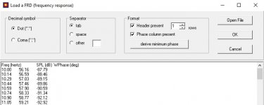
I succeeded to load both lists (with tab as the separator and with ticked "Header present" and "price column present" options).
I doubt that. But I didn´t use the program for some months, the computer maybe was updated etc etc etc so anything can have happened. I can try to open them and save them with non-ANSI encoding (if I figure put how to do that) and see if things change.
I could try to investigate this if you share your design file. You can attach it here or send it to xmachina.ai@gmail.com
Also intereested in the baffle diffraction (what to use, and to have it in this program in the future)")
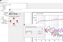
Influence of the front baffle is included in the measured frd characteristics.
Hi!
I made regular use of XMachina w/o any problems, just one thing remains not completely clear to me, in the task chart the strategy strenght option, what exactly changes betweeen "delicate" and "strong"
This is about the component reduction strategy:
- if you want a simple circuit (but possibly less aligned with the targets) move the slider towards "strong";
- if the goal is maximum compliance with the desired characteristics (and other targets) and circuit complication is not a problem, move the slider towards "delicate".
Increasing/decreasing the "+-" value makes XMachina more/less sensitive on the errors with relation to the target characteristic.and in wich way it is different to the (+ / - dB) accuracy option.
Both parameters ( the slider position and the "+-" value) contribute to the total learning index and can have similar impact on the results.

Need hlp
Hi, on my System (Win10, 20H2 last Build on Dell M3800) is something happen:
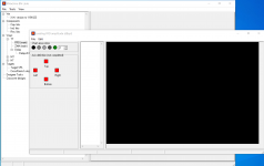
I select 'Load FRD from Picture', then the context menu with the right mouse button. The message in the popup box is followed and ... Yihaa .. a black screen appears. It's a shame because I have no idea what's going wrong there. Unfortunately the PDF is no help either.
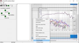
This is also the case with the woofer tool, here I don't know what is required, as it is also not available in the pull-down menu. (pls Look at the last Picture)
Hi, on my System (Win10, 20H2 last Build on Dell M3800) is something happen:
I select 'Load FRD from Picture', then the context menu with the right mouse button. The message in the popup box is followed and ... Yihaa .. a black screen appears. It's a shame because I have no idea what's going wrong there. Unfortunately the PDF is no help either.
This is also the case with the woofer tool, here I don't know what is required, as it is also not available in the pull-down menu. (pls Look at the last Picture)
Attachments
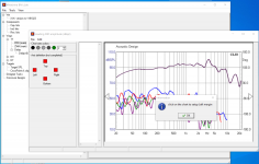
Strange. I'm trying to reproduce this effect in my system (also Win10) but I can't. Question: did the window went black when you clicked OK in the "left margin" message box or when you clicked your chart to define the margin? Or another moment?
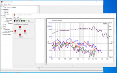
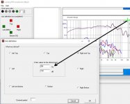
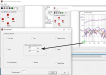
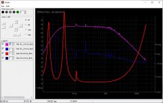
Just one thing that I noticed (which may or may not be related to the problem) is that your axes are undefined. Click a point on the chart and enter corresponding freq and dB values, for example:

Then click another point an do the same:

From this moment you can digitize the curve manually clicking on it.
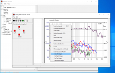
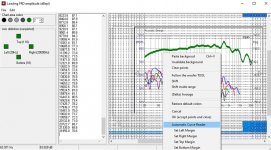
But if you want to use automatic digitization, first narrow the picture processing area on the chart with the margins (use the context menu) :

Choose "automatic reader" from the menu and finally click on the curve to get it digitized:

If you're satisfied with the effects, use "accept the points and close" from the context menu. Your curve will be transferred to the FRD node. (But if something went wrong with automatic reading you can select "clear points" from the menu and try again).

Just one thing that I noticed (which may or may not be related to the problem) is that your axes are undefined. Click a point on the chart and enter corresponding freq and dB values, for example:
Then click another point an do the same:
From this moment you can digitize the curve manually clicking on it.
But if you want to use automatic digitization, first narrow the picture processing area on the chart with the margins (use the context menu) :
Choose "automatic reader" from the menu and finally click on the curve to get it digitized:
If you're satisfied with the effects, use "accept the points and close" from the context menu. Your curve will be transferred to the FRD node. (But if something went wrong with automatic reading you can select "clear points" from the menu and try again).
Attachments
Hmm, my Win 10 is a 64-bit version.
Unfortunately, I can't even define the margin. When I open 'Load FRD from Picture' for the first time after launch and select and paste the .bmp, it is displayed as a picture. The directly following left click does not trigger a reaction, a right click brings up the context menu as in my 2nd picture. So I cannot define the frame, because the color of the Corsor-X does not go to 'green' either. As soon as I make a choice in the context menu, however, the image turns into a black area.
I close the window with 'X', open it again and ... again the black area.
The surface only turns white again when the application is completely closed. But then it starts all over again ...:verwirrt:
I would also like to know what exactly I have to do with the Follow The Woofer Tool so that I can go further, but that is the further construction site.:Ö
thx
I could try to investigate this if you share your design file. You can attach it here or send it to xmachina.ai@gmail.com
Thanks. I will send them.
Influence of the front baffle is included in the measured frd characteristics.
I will take a look in that. Where to put in the baffle size, angle, driver position etc into XMachanik
The next thing is also room compensation. Like what if: Distance from back of cabinet to the wall......, to the corner......
The Genre i didn´t find.
The Edge creates compensation links for a cross over. Dont really understand how i get those into XMachina. Also a bit strange to me (but what do I know) that it doesn´t use the specific driver in the calculation.
I think that I was looking for something that actually produce adjusted spl output, impedance and "what more" graphs based on a driver, a baffle and a specific position on a floor with length to the wall behind (and possibly to the sidewall and the roof).
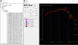
Hmm. Tried to import (space separated) Frd and Zma files. None of them worked. When trying the Frd filen from Hornresp i get this error message. And Yes I select that there is one header row, that the file is space separated and I take away everything from 10kHz because of a space problem.
Attachments
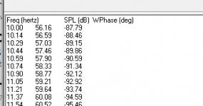
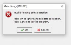
Please attach the files you are trying to import.Hmm. Tried to import (space separated) Frd and Zma files. None of them worked. When trying the Frd filen from Hornresp i get this error message. And Yes I select that there is one header row, that the file is space separated and I take away everything from 10kHz because of a space problem.
Where to put in the baffle size, angle, driver position etc into XMachanik
The next thing is also room compensation. Like what if: Distance from back of cabinet to the wall......, to the corner......
Have you heard of the ViuixCAD? This may be what you are looking for.
When I find an interesting result in XMachina, I usually transfer it to ViuixCAD for further analysis and modifications.
Hmm, my Win 10 is a 64-bit version.
Unfortunately, I can't even define the margin. When I open 'Load FRD from Picture' for the first time after launch and select and paste the .bmp, it is displayed as a picture. The directly following left click does not trigger a reaction, a right click brings up the context menu as in my 2nd picture. So I cannot define the frame, because the color of the Corsor-X does not go to 'green' either. As soon as I make a choice in the context menu, however, the image turns into a black area.
I close the window with 'X', open it again and ... again the black area.
The surface only turns white again when the application is completely closed. But then it starts all over again ...:verwirrt:
64-bit shouldn't be a problem. My system is 64-bit too. Since I cannot reproduce the effect im my system I have to honestly admit that i have no idea how to help.
Maybe someone had a similar problem and can share his observations?
I would also like to know what exactly I have to do with the Follow The Woofer Tool so that I can go further, but that is the further construction site.:Ö
"Follow the woofer" tool is not intended for curve digitization, it's for target system response setting. It should be disabled in "Load from picture" window (I will fix that).
The idea came from the observation that correcting the low frequency response with a crossover filter would likely require the use of large, heavy and expensive coils and capacitors. Therefore, it is worth setting the target system characteristic so that the filter in LF range does not correct anything, i.e. it is transparent or, in other words, target characteristic follows the woofer characteristic. And the rest of the target system characteristic is set as desired.
Have you heard of the ViuixCAD? This may be what you are looking for.
When I find an interesting result in XMachina, I usually transfer it to ViuixCAD for further analysis and modifications.
Ok. So that's the process. I thought it might be the other way areound.
So in my case with a MLTL I could go Hornresp/MathCAD output + Tweeter info => XMachina output transfer (How???) to => VituixCAD for adjustment based on baffle diffraction etc?
But then what? Do you normally start again, or how does the "loop" look like?
Box design => Xmachina => VituixCAD => Box design => Xmachina => VituixCAD etc
OR
Box design => Xmachina => VituixCAD => Xmachina => VituixCAD etc (without starting over with box design because it´s not normally necessary, or?)
Enclose two examples of Frd and Zma files. I have tried to create other versions through MS Word etcd.
Attachments
On the weekend I installed XMachina on another Win10-64 bit Dell notebook (7470 / i7) and an ancient Samsung Win 7/32 ... strangely, the same effect, the image recognition does not work. However, the same function with VituixCAd works with their.
It may be helpful to allow other image formats such as jpg and / or png.
Fortunately, I can help myself with it.
It may be helpful to allow other image formats such as jpg and / or png.
Fortunately, I can help myself with it.
^Actually you can forget about picture formats working with "Load from picture" window.
The easiest way is to copy - paste your chart. Don't mind whether its jpg or png displayed just do Alt-PrintScreen in the browser (or any other window) and Ctrl-V in XMachina "Load from picture" window. You'll get also the window frame pasted but it's not a problem. That's what the margins are for, narrow the picture processing zone with the margins, and proceed with the "automatic curve reader" tool.
Manual digitizing is quite effective too, no needing to setup the margins just click on the curve. With manual digitization you also don't care about noisy or repeated colors.
And finally I can see the reason of the problem - there is a bug in "Load picture" option From the File menu. Don't use it. Use copy paste instead. I can reproduce all the effect you were reporting, thank you for notifying.
- Home
- Design & Build
- Software Tools
- Automatic crossover designing with XMachina