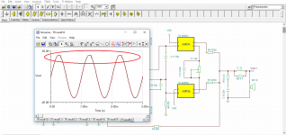
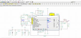
I try to simulate an amplifier with tina ti. Steady State Solver analysis result like that.Firstly are we need this analysis to test amplifiers performance? Secondly the result seems not normal.Am i right and where must be problem ?
My best
My best
Attachments
Increasing the supply and seeing the issue resolve makes sense but I would still expect it to clip as before if you rise the input a little.
Your image shows only around +26 swing which seemed low for a 40 volt rail.
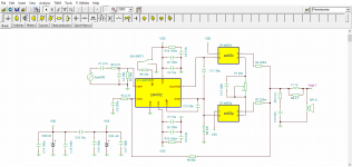
Increasing the inductor resistance should reduce Vout because that resistance is now in series with the load, but the main amplifier output (junction of the two 0.22 ohm resistors) should remain the same, possibly with less clipping as the load is a little easier.
Your image shows only around +26 swing which seemed low for a 40 volt rail.
Increasing the inductor resistance should reduce Vout because that resistance is now in series with the load, but the main amplifier output (junction of the two 0.22 ohm resistors) should remain the same, possibly with less clipping as the load is a little easier.
When i make supply voltage 40V to 45V it resolved.Also without change 40V when i increase resistance of inductor sinus was resolved.I hope these are true ways.
Higher supply does resolve the clipping. That is to be expected. What was the supply in the first post with the clipping?
If I remember correctly, the Sanken output devices are darlingtons so need more Vce, thus will clip relatively early.
I see nothing strange in your first picture; positive clipping, and some 'sticking' is normal.
I don't think there is a specific 'problem'. As to whether this is a good way to test an amplifier, sure, if you want to know max output level, and calculate max output power, you set the supply to what you have and increase signal until clipping. It is not fully accurate because in practise the supply will sag with output current, and a speaker is not a resistor. But it give an good approximation.
Edit: I see, the battery was 40V. I agree with Mooly, 26V clipping is early with 40V. But doesn't the driver chip limit it?
Jan
Last edited:
Hi Alchamist,
I'm probably too inexperienced with simulators to be sticking my big snout in here, but the STD03x parts got me curious, so I looked 'em up . . Are you sure you have them wired up correctly? I assume that you could have rearranged the pinouts in the models, but according to the mfg's data sheets:
there is no pin 4,
pin 3 is the collector,
pin 1 is the base,
pin 2 is/are the loose end of the bias diode(s).
Even if everything is connected in the usual common-collector manner, C11 and R6 are still a puzzle. Especially the latter, since at +26V output, it adds another .5 mA to the already meager 3 mA the 4702 can provide -- is there an application note that I could 'learn up' on this technique?
Regards,
Rick
Mr.Didden ,
Thank you for your advise and accutally swing is 24,5V. As i said there is not clipping with 45V rail when input signal is 1V/1khz. Will i have a problem with sound in this way or the amplifier will work fine ?
Hi Rick PA Stadel,
The pins connections are ok. You right std03 has 5 pin but pspice code was written for 4 pin because one of them don't use as you know and simulation auto create the symbol with 4 pin.
I couldn't understand your comment about currents but i benefited from AN-1490 . My C11 is Cb3 and Cb5 in this app report. Also R6 is not seem in AN-1490 but i put it to reduce second harmonic.
My Best
- Status
- This old topic is closed. If you want to reopen this topic, contact a moderator using the "Report Post" button.
- Home
- Design & Build
- Software Tools
- Steady State Solver Question