I've made a bit of progress on simulating an OB. But my OB has 2 woofers in parallel per side and that has caused a new confusion.
Option 1.
- In enclosure tool set count=2 and woofers in parallel
- Generate 2Pi and Impedance responses.
- In diffraction tool set count=2, position drivers on baffle and set 2Pi from earlier step
- Generate Full space responses
- In Main screen enter only one woofer and set full space responses and impedance from above.
- In crossover create 2 speakers and for each select the same driver. Set X,Y relative positions
Option 2.
- In enclosure tool set count=1
- Generate 2Pi and Impedance responses.
- From diffraction tool generate separate responses for each woofer based on their position using the 2Pi response from earlier step
- Generate Full space responses for each woofer separately
- In Main screen enter 2 drivers representing each woofer
- For each woofer load the respective diffraction responses.
- In crossover create 2 speakers and for each woofer and select respective driver. Set X,Y relative positions
Which of the above is right? Option 2 seems right.
my OB has 2 woofers in parallel per side.
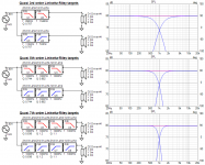
What is this? OB has usually one...several drivers in open baffle so that rear side of the cone/surface produces rear wave.
Anyway, recommended procedure if measurements are not available and possible is to simulate single driver with Enclosure tool as Infinite baffle, export and load 2pi response to Diffraction tool and simulate off-axis responses with 'Open baffle' checked. Export off-axis responses from Diffraction tool and load freq. responses to single driver in Drivers tab in the main program. Add two driver instances to XO nework and use the same response data if radiators are acoustically close to equal.
Simulate LF drivers separately in Diffraction tool if they are acoustically very different. Then you need to export off-axis responses from both diffraction simulations, and add two drivers to Drivers tab in the main program. Two drivers in XO nework linked to different frequency responses.
Impedance is exported from Enclosure tool. It's usually for single driver because final quantity and electrical connection is designed in XO network.
Last edited:
Hi Kimmo,
I've found a very insignificant but for the sake of it here it is:
In Auxiliary tool, box volume, internal width (see picture). Calculation of net volume is ok.
And I have a request if possible, we can export listening window (for example) It would be nice to be able to export impulse response of listening windows (for example) in a format that would be compatible with Hypex HFD software import.
Jean Claude
Attachments
Member
Joined 2003
What would be even nicer would be for Hypex HFD to support frequency response data import instead of requiring impulse response. This basic feature was promised years ago but never delivered. But...you can do all the work in VituixCAD, then just copy the filter configuration over to HFD
In Auxiliary tool, box volume, internal width.
Noted. Will be fixed when brain works
")
It would be nice to be able to export impulse response of listening windows (for example) in a format that would be compatible with Hypex HFD software import.
Original target was that filter parameters are designed with VituixCAD and then entered to filter designer software of selected gear such as Hypex. Reason is that manufacturer's software is not able to manage quasi full space i.e. includes assumption that single response represents full space or behavior in full space is possible to predict/guess otherwise. Equalizing passive speaker with DSP app. is different case because directivity index is locked with passive XO.
Special problem with Hypex is that they were not able to tell how biquad coefficients are calculated so VituixCAD is not able to emulate exact transfer functions for Hypex. This is one reason (in addition to reliability) why I can't recommend Hypex.
One tiny feature related to LW exported via File->Export->Listening window is that amplitude response is R.M.S and phase response is based on sum (without power of 2 and square root) so phase features compared to minimum phase are not exactly maintained.
But if that does not matter, you can export LW as frequency response file and load it for driver in another VCAD project with single wire as XO. Then export total SPL as impulse response for Hypex as wav file from Impulse response window.
Thanks Kimmo,
Unfortunately, loading LF in a new project and exporting LW as impulse response windows does not work for me. I got a flat freq curve in Hypex.
Anyway, I will continue as before that is using VCAD for all my simulations, import filters in Hypex and measure the results with slight adjustments.
Jean Claude
What is this? OB has usually one...several drivers in open baffle so that rear side of the cone/surface produces rear wave.
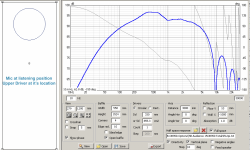
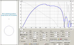
Thanks Kimmo. I'm trying a FAST with 2 woofers and a full range per side.
I'm new to this so please bear with me.. There are few things still tripping me..
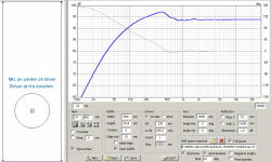
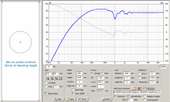
1. Although the woofers are identical the diffraction varies with mic position especially if the mic is on center of the driver.
The Measuring with REW doc says "Elevation of mic is at the center point of driver under test i.e. mic and driver have the same Y-coordinate in mm." but the video tutorial says to adjust mic position. Far field measurements I've seen are done with mic on design axis (along tweeter/mid/in-between) for all drivers.
I'm also reading this article by wintermute and tried using VituixCad for simulating diffraction on an IEC baffle and was able to match the response from Bagby's spreadsheet only when the mic was along the center of the driver. Also, since Bagby's sheet doesn't accept a mic position is it always on the center of the driver?
So mic along center of driver or along design axis? Or depends what the diffraction is for?
2. If we've got the diffraction as per driver position on the baffle why does the crossover section again have X/Y/Z? Should I translate the baffle X/Y into the relative X/Y for the crossover?
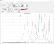
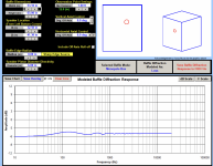
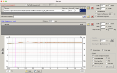
3. The amplitude for the IEC baffle response from Bagby's sheet does not match what I get from VituixCad (last 2 images). I assume I have to scale the response. But what do I scale it to? I've attached a pic after loading into the Merger tool. I'm trying wintermute's idea to subtract the IEC baffle response from manufacturer trace.
Attachments
-
 Screenshot 2021-07-15 at 7.03.36 PM.png692.2 KB · Views: 324
 -
 Screenshot 2021-07-19 at 7.56.24 AM.png707.7 KB · Views: 282
 -
 Screenshot 2021-07-15 at 7.02.51 PM.png767.7 KB · Views: 278
 -
 Screenshot 2021-07-15 at 7.02.28 PM.png746 KB · Views: 274
 -
 Screenshot 2021-07-21 at 8.35.50 AM.png932.9 KB · Views: 273
 -
 Screenshot 2021-07-21 at 8.48.10 AM.png687 KB · Views: 91
Member
Joined 2003
1. There’s little reason to not measure on the driver axis when using a 2-channel measurement system. Any references elsewhere I would expect to be referencing methods for single channel measurement like USB mic where time of flight for acoustic delays cannot me included on in the measurement. Follow the design guide documents for VituixCAD.
Always simulate diffraction at your mic location, as the intent is to fill in low frequency information that is not available in the far field gated measurement.
2. If you’ve measured correctly keeping same distance from mic to baffle and keeping same FFT start when processing the impulse response, then Z offset can remain at zero as the delays are included in the measured data. This is provided your drivers are on a flat baffle. Enter x and y for other drivers in relation to the tweeter, keeping tweeter at 0,0,0 provided you want on axis with tweeter as your design axis.
3. Not sure what you're doing with that merger tool. The low frequency measurement portion is for the near field response, the diffraction response gets loaded into the section labelled "diffraction response". Again, follow the design guide documents would be the best place to start. There's no need to use Jeff's old spreadsheets when using VituixCAD, all the tools needed are available within VituixCAD.
To "subtract" the diffraction from manufacturer trace, you must know the IEC baffle as well as measured mic distance. You may find that given the IEC baffle and mic distance the impact of completing this task to try to create a true 2pi response is rather minimal. In any case, the calculator tool is what you want to use, try the "divide" function.
Last edited:
I have a little question or suggestion for the trace calculator.
Is it possible to calculate the ratio or proportion of two (or multiple) graphs and export (or show) this in percentages?
Usually I do this in Excel, by calculating graphs in dB back to linear values, but that is very tedious process.
Is it possible to calculate the ratio or proportion of two (or multiple) graphs and export (or show) this in percentages?
Usually I do this in Excel, by calculating graphs in dB back to linear values, but that is very tedious process.
Last edited:
Member
Joined 2003
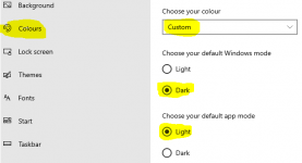
Thanks for pointing out those settings. I hadn't seen the "custom" setting before. My preference would be to have control within VituixCad. It is one of few apps I prefer the brightness high - the crossover section is especially cluttered feeling and hard to see for me with the grey on grey dots on black background.
Other than that, maybe I just need a few days to adjust mentally
I really appreciate this amazing tool that you've put into the world and are constantly developing. Thank you.
Other than that, maybe I just need a few days to adjust mentally
I really appreciate this amazing tool that you've put into the world and are constantly developing. Thank you.
- Home
- Design & Build
- Software Tools
- VituixCAD