Well, it's doing the same with every single driver. Even large subwoofers have perfectly flat response up to 40k.
Frequency response extends to infinity with traditional T/S model if voice inductance parameters are ignored. So flat to 40 kHz and beyond is fully expected with simplified theory - though it's not fact IRL.
Another option is to enable inductance parameters: plain Le, basic impedance model or extended impedance model. It's 'Show effect of inductance' command in context menu of SPL chart. That's not exact fact either. Read user manual please.
Ok thanks,
I have read the help section of the program. Is there another manual? I cannot find where to input Le or any inductance parameters. I don't see where I can enable inductance parameters when generating a frequency response chart.
What is the menu of the SPL chart? I can't find any menu associated with this. I'm very sorry for all of the questions. I have read all the resources I could find before reaching out here, and I'm very grateful that you've responded. Other than this thread, I have only found the help section of the program.
I will keep looking for how to enable the inductance parameters or apply the impedance model. Even impedance model would be enough for my purposes, as we will be testing accurately in anechoic chamber ultimately. I'm not expecting this software to give me accurate FR, just the general response.
")
Or how to get FR to follow impedance model, for example?
You need to measure both impedance and frequency response. Load them to your driver, then you will be able to simulate the effects.
Ok I've got it now. Thanks all, much helpful.
For some reason, in the nightclub industry where I worked before this year, it only became typical to use modelling software much later, and I found it easier to dial it all in by ear rather than mathematically/with measurements
I'm so amazed that there is this incredible free tool!! Very very happy with the quality of help I've gotten here! it's a great time to be doing this stuff. Being able to model biquads --- wow nice feature!!!
Last edited:
I see odd behavior using the basic impedance model with multiple drivers in series. Best I can tell, parallel connections, plain Le, and extended models work consistently. This does not affect all drivers! 15W/8434 & NE123W-08 are good examples in the standard database.Another option is to enable inductance parameters: plain Le, basic impedance model or extended impedance model. It's 'Show effect of inductance' command in context menu of SPL chart. That's not exact fact either. Read user manual please.
To reproduce:
- Show effect of inductance.
- Plot to 20kHz.
- Select a driver with values for Z1k & Z10k.
- Increase the driver count.
- Note changes in HF impedance & corresponding FR.
NE123W shows strange results with 3x & 12x drivers but not the other configurations. Weirder, its HF Z increases, which is opposite to other drivers I've checked.
^Multiple problems in basic impedance model solver fixed/improved to rev 2.0.58.1 (2020-11-29)
Enclosure
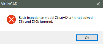
* Initial values, constraints and parameters of basic impedance model solver improved to support all driver models, quantities and connections. May still fail with tweeters and illegal combinations of Z1k and Z10k.
Error message if basic model fails:
Enclosure
* Initial values, constraints and parameters of basic impedance model solver improved to support all driver models, quantities and connections. May still fail with tweeters and illegal combinations of Z1k and Z10k.
Error message if basic model fails:
Attachments
Last edited:
Hi Kimmo--
I am wondering if this is a bug. I exported a flat FR (no half-space response loaded) from a pseudo-infinite baffle diffraction sim (10000mmx10000mm). Shouldn't all of the off-axis angles be at the same level before beaming sets in? I don't have 'open baffle' checked, so I don't think there should be any cancellation from the back-wave.
Thanks!
--Myles
^Diffraction tool is not designed for any kind of infinite baffle simulation. That wouldn't make much sense if we're talking about box/baffle diffraction to far field = intended purpose of the tool. In addition, DED model used in the simulation doesn't have exceptions for near field simulation within the edges.
So at the moment without adaptive constraints in dimension parameters user should take care that edge cannot rotate to the "back side" of virtual microphone with any horizontal or vertical off-axis angle. I can add adaptive constraints if that helps to avoid mistakes.
Flat rigid piston directivity simulation in Calculator tool is more suitable for simulation to half space only, though actual radiators are not flat rigid pistons i.e. result is not very valuable in practice.
- Home
- Design & Build
- Software Tools
- VituixCAD