Draki, thank you very much for this help. I'm going to see how this happened. RickThe near-field (low frequency part) should be brought up to 95 dB level with the scale/dB feature.
Now it is at -40 dB or so.
Its not auto-updating. Looks like you may not have bumped the rev level
I don't increase revision anymore if just tweaking some invisible feature by request. Hopefully auto-update once or twice a week is okay for the others.
I don't increase revision anymore if just tweaking some invisible feature by request. Hopefully auto-update once or twice a week is okay for the others.
I installed it over top of existing installation and the changes seem to work!
Thanks.
Hello colleagues! I have a question related to the minimum phase. I want to know the offset of the tweeter for the manufacture of a step baffle. I will tell you in detail.
1. I created a mock speaker box and made the following measurements.
a) Tweeter on the axis. 1 meter to the microphone.
b) Tweeter and midbass together on the axis of the tweeter. 1 meter. Target response.
c) Midbass on the axis. 1 meter.
I made all measurements in REW.
Now the main thing. If I extract the minimum phase using REV, I get a tweeter acoustic center offset of 17mm. If I extract the minimum phase using the VC, I get a tweeter offset of 8mm. The difference is 9mm. It's a lot. What could be the mistake? Thank!
c) Midbass on the axis. 1 meter.
What axis? Tweeter's axis as while measuring a) and b) or something else?
Typically all measurements are captured mic at the same spot (on design axis) with this method.
What could be the mistake?
Could you attach all measurement files or send by e-mail if measurements were taken with the same mechanical and electrical settings.
P.S. I suppose you know that this is not recommended method due to poor off-axis support and nonobjective part in minimum phase calculation.
Hi Kimmosto, hope you are well. Two feature request that I thought I'd put out there ")
I use VituixCAD a lot for generating CTA-2034A plots and seeing how tweaks affect them. Would you consider:
-Allowing us to export all CTA-2034A curves at once. It gets a little repetitive exporting all seven curves individually when iterating rapidly.
-Since the change to the Early Reflections curve calculation means you now calculate the invididual Front, Side, Rear, Ceiling, and Floor reflections separately to compute the total curve, would you consider allowing us to export the individual components?
And perhaps also the Total Horizontal (Front, Side Rear) and Total Vertical (ceiling, floor). I like being able to see each part and though I can of course do that manually, it would also be a time saver.
Thank you for considering!
^Do you prefer multiple separate two-column files or single multi-column file?
Multiple two column would be best as I usually go back and forth with REW. Thank you!
Rev. 2.0.50.5 (2020-05-23)
Main program
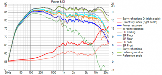
* Added optional ER front, ER side, ER rear, ER floor and ER ceiling curves to Power & DI graph.
* Added 'Show Early reflections 5' to context menu of Power & DI graph to show/hide previous five curves.
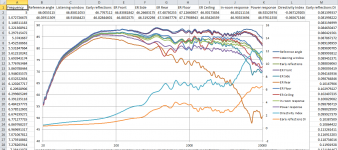
* Added File->Export->CTA-2034-A data for exporting curves in Power & DI graph as multi-column csv file or 12 separate txt/frd files.
Excel reads multi-column csv without problems.
Main program
* Added optional ER front, ER side, ER rear, ER floor and ER ceiling curves to Power & DI graph.
* Added 'Show Early reflections 5' to context menu of Power & DI graph to show/hide previous five curves.
* Added File->Export->CTA-2034-A data for exporting curves in Power & DI graph as multi-column csv file or 12 separate txt/frd files.
Excel reads multi-column csv without problems.
Attachments
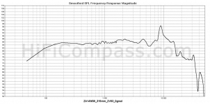
Sorry to interject a basic dummy question, but is there a trick to getting Grid Removal to work in SPLTrace? I'm trying to trace some results from HIFICompass measurements, and grid removal just does nothing whether I select an open area in the 'first' cell or try to hit the grid lines themselves. Tracing with the grid lines is a mess, so it seems that it's necessary to remove them.
The results separate out spl from Z, but I'd imagine that for grid removal that shouldn't matter.
Attached is an example that I'm trying to trace.
The results separate out spl from Z, but I'd imagine that for grid removal that shouldn't matter.
Attached is an example that I'm trying to trace.
Attachments
Its the transparency of the PNG that causes the issue. Converting to JPEG solves it.
You are correct, sir. Thanks!
^Never before because File->Export->Filter response of Driver (earlier Filter gain of Driver) has been obvious and perfectly intuitive for everybody so far. If not intuitive enough then RTFM Impulse response window provides export as IR in 12 other file formats.
'Driver overlay' sounds that you are talking about Enclosure tool? Main program shows continuously electrical and acoustical axial responses of all drivers connected to XO. Enclosure tool provides single overlay in SPL graph, but tree other methods to compare different drivers:
- Saving and switching/toggling different enclosure projects with arrow down button on the right side of open Project button.
- Scrolling drivers selected from database (Sel field and Enable filtering checked) with Auto align on. This automatically aligns closed and vented box when driver selection is changed.
- Scrolling drivers selected from database with Auto align off. This changes driver, but maintains volume, vent size, tuning, Q factors etc.
Impulse response window provides export as IR in 12 other file formats.'Driver overlay' sounds that you are talking about Enclosure tool? Main program shows continuously electrical and acoustical axial responses of all drivers connected to XO. Enclosure tool provides single overlay in SPL graph, but tree other methods to compare different drivers:
- Saving and switching/toggling different enclosure projects with arrow down button on the right side of open Project button.
- Scrolling drivers selected from database (Sel field and Enable filtering checked) with Auto align on. This automatically aligns closed and vented box when driver selection is changed.
- Scrolling drivers selected from database with Auto align off. This changes driver, but maintains volume, vent size, tuning, Q factors etc.
- Home
- Design & Build
- Software Tools
- VituixCAD