I don't understand this comment. Why should a 4th order Linkwitz Reily crossover necessarily cause such a severe impedance dip ?
I'm just guessing now: probably traced SPL curves without post processed conversion from half space to full space (missing BSC) has caused sensitivity error of 3...5 dB to woofer which could cause bad impedance issue if (traced) magnitude responses of mid or tweeter needs also lifting close to crossover frequency with high Q of LCR. This would be just illegal data used for simulation, though it's possible to select drivers in practice so that frequency response has dip(s) without small amplifying of driver's voltage with resonance of LCR.
Perhaps Oneminde could confirm has 4th order been an issue also with some actual and valid data.
Rev. 2.0.34.0 (2020-01-09)
Auxiliary calculator : Time align
* Added manual scaling for Sum measurement, -1.0...+1.0 dB.
* Added auto scaling for Sum measurement; click dB label on the right side of value field.
* Error value and background color are updated also while manual adjustments.
* Improved LF delay solver to handle also bad initial values.
Direct me where to go if this isn't the correct thread for this, but it seems like it. I am running Vituix in a bootcamp environment on Windows 7 Pro. When I import an frd or zma file nothing happens. Files were created in Vituix with the tracing tool. I am at a loss as to what I am doing wrong. I don't have the "visible" checkboxes (see screenshot).
Attachments
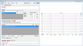
^I guess you have not added a wire from the generator to the driver?Tip 2
I pulled them into Xsim and they displayed. Its likely the issue is with my bootcamp implementation. I have issues similar to this with other programs in the past. My bootcamp environment is shakey at best.
Thanks for the tip. I just wanted to make sure I wasn't missing anything obvious.
^Yes it is. MLSSA .txt is suitable file format, but you need to delete three rows from the beginning for HFD import, for example:
0
0.0208333333333333
262144
which are: just 0, sample interval in milliseconds and number of samples.
MLSSA .txt export is available in 'Convert IR to FR' (small export button on the right side of file list) and Impulse response window. The first one is able to export raw measurements only which is okay for small mids and tweeters. The last one is most suitable for post processed responses such as merged to LF near field sum * baffle effect response + HF far field response.
BUT HFD is not the best tool for designing crossover for multi-way from the beginning because acoustical off-axis, power & DI are not available. It could be valuable for fine tuning with measurement data, but important decisions should be done by full simulation. But this is common problem with filter designers of many...all dsp manufacturers.
what would be the best way to model for floor reflections in the diffraction tool when the baffle is angled backwards (-10 deg from vertical plane)? I am building some floor standing speakers where the woofer is mounted fairly low to the ground however the entire enclosure is wedged by about 10 degrees.
also, are there any other locations that the tilted baffle would need to be accounted for? I have calculated the distances between drivers and will be placing them such that woofer voice coil is about the same distance as the tweeter from the listening position (i.e. tweeter will be further back and woofer forward due to the tilted baffle).
also, are there any other locations that the tilted baffle would need to be accounted for? I have calculated the distances between drivers and will be placing them such that woofer voice coil is about the same distance as the tweeter from the listening position (i.e. tweeter will be further back and woofer forward due to the tilted baffle).
^Tilting is not possible with Diffraction tool so baffle is simulated in vertical position. Usually the lowest XO frequency is low compared to directivity of cone and box so simulation with tilt would not make significant difference.
Excess delay could cause small problem to phase response if elevation difference (Y coordinate) of driver and virtual microphone is high. Delay can be removed from baffle effect response with Minimum phase A function of Calculator tool.
Probably the biggest uncertainty is defining attenuation of floor reflection. I think perfect reflection producing 6 dB gain is not the best option producing too low "average" pressure for woofer. About "double power" could be more correct estimation so one option is to attenuate floor reflection until diffraction simulation produces total baffle step of 3 dB, and then axial response is designed flat with the main program.
Second option is to leave floor reflection unchecked and reduce axial distance until total baffle step is about 3 dB, and then axial response is designed flat with the main program.
Third option is to leave floor reflection unchecked and simulate diffraction to the longest possible listening distance e.g. 5000 mm and design axial and power responses with the main program so that power response stays constant (flat horizontal) below the lowest crossover frequency. This is what I would probably do because method takes into account also directivity of LF radiator. Inroom SPL at listening spot could be a bit too high at LF, but correct level is subjective anyway and depending on listening environment and setup i.e. speaker & listener locations.
Driver measurements 0-180 deg according instructions; mic perpendicular to driver (speaker tilted vertically while off-axis measurement sequencies). Drivers located to simulation according final reality i.e. Z coordinate and T tilt varies for each driver.
And finally, I would not locate single woofer very close to floor")
Excess delay could cause small problem to phase response if elevation difference (Y coordinate) of driver and virtual microphone is high. Delay can be removed from baffle effect response with Minimum phase A function of Calculator tool.
Probably the biggest uncertainty is defining attenuation of floor reflection. I think perfect reflection producing 6 dB gain is not the best option producing too low "average" pressure for woofer. About "double power" could be more correct estimation so one option is to attenuate floor reflection until diffraction simulation produces total baffle step of 3 dB, and then axial response is designed flat with the main program.
Second option is to leave floor reflection unchecked and reduce axial distance until total baffle step is about 3 dB, and then axial response is designed flat with the main program.
Third option is to leave floor reflection unchecked and simulate diffraction to the longest possible listening distance e.g. 5000 mm and design axial and power responses with the main program so that power response stays constant (flat horizontal) below the lowest crossover frequency. This is what I would probably do because method takes into account also directivity of LF radiator. Inroom SPL at listening spot could be a bit too high at LF, but correct level is subjective anyway and depending on listening environment and setup i.e. speaker & listener locations.
Driver measurements 0-180 deg according instructions; mic perpendicular to driver (speaker tilted vertically while off-axis measurement sequencies). Drivers located to simulation according final reality i.e. Z coordinate and T tilt varies for each driver.
And finally, I would not locate single woofer very close to floor
Hello kimmosto, wouldn't it be a good idea to make the enabled "crossover variant" button a bit darker/more contrasting?
I mean a darker button background so that it's really in your face...
I see it has a dark border and a darker background when selected, but I think it's not dark enough?
Or maybe also make the text bold?
It already happened a few times... comparing multiple versions and editing/subconsciously saving into the wrong one, when I notice it's too late...
Last edited:
Hi,
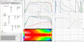
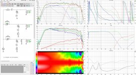
I designed simple 2,5way crossover. I wanted to achieve:
1. flat frequency response
2. flat directivity index
3. good impulse response
4. flat impedance and phase
It all ended up in very low impedance of 2,1 ohm. Do you think it is an issue if you use D-class Hypex amp that is capable of 2ohm load?
If you see sth wrong in the crossover please let me know. I just wanted to ask you for your opinion guys before I order components. Tweeter is mounted in a waveguide that is why I use little value of HP capacitor.
Thank you!
Attachments
This is not worth stressing your amp over. Maybe it is good sometimes, but most amps do not need you to do this.4. flat impedance and phase
Your first problem is the 5.6 ohm and 6.8 ohm resistors. At low frequencies these are across the amp outputs. Together they are 3 ohms.
^Selected variant is with Bold font in the latest build of 2.0.34.0 (2020-01-18)
The latest 2.0.34.0 shown is 2020.01.09 ?
Hi Kimmosto:
Please help me understand what I've been doing with Vituix
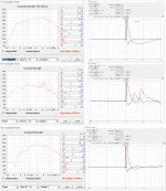
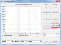
I've been modeling a transmission line subwoofer in HornResp. I needed to export from one of its screens that doesn't support export directly so I did a screen capture and then dropped the screen into your trace SPL tool. Trace gave me an SPL text file containing both amplitude and phase. Am I correct in assuming that Vituix derived minimum phase from the amplitude function that was traced? But I don't think the composite output of a Tline can be considered minimum phase...hence my question.
So I repeated this process for separate Tline and front of cone outputs separately. The output for the "optimally" damped Tline shows an IR with 3 peaks of decreasing amplitude as one might expect, given partially damped reflections from the ends of the Tline. So perhaps the minimum phase assumption isn't too far off?
The cone output looked like what one would expect from a direct radiator and clearly the simulated response of a direct radiator would be minimum phase.
I would love to be able to load both responses into a Vituix crossover-less model and add delay until they sum as in HR because I don't trust the IR derived from the screen capture of the HR model. I can point a single driver to each response separately and see its FR and IR in Vituix. But when added, the 2nd driver gets ignored. The crossover is just a piece of wire connecting both D1 and D2 to the source. I haven't created any directivity files. I'm guessing Vituix sees something wrong with or missing from the model that causes it to decline to include D2 in the response. Any idea what it might be?
Thanks,
Jack
Please help me understand what I've been doing with Vituix
I've been modeling a transmission line subwoofer in HornResp. I needed to export from one of its screens that doesn't support export directly so I did a screen capture and then dropped the screen into your trace SPL tool. Trace gave me an SPL text file containing both amplitude and phase. Am I correct in assuming that Vituix derived minimum phase from the amplitude function that was traced? But I don't think the composite output of a Tline can be considered minimum phase...hence my question.
So I repeated this process for separate Tline and front of cone outputs separately. The output for the "optimally" damped Tline shows an IR with 3 peaks of decreasing amplitude as one might expect, given partially damped reflections from the ends of the Tline. So perhaps the minimum phase assumption isn't too far off?
The cone output looked like what one would expect from a direct radiator and clearly the simulated response of a direct radiator would be minimum phase.
I would love to be able to load both responses into a Vituix crossover-less model and add delay until they sum as in HR because I don't trust the IR derived from the screen capture of the HR model. I can point a single driver to each response separately and see its FR and IR in Vituix. But when added, the 2nd driver gets ignored. The crossover is just a piece of wire connecting both D1 and D2 to the source. I haven't created any directivity files. I'm guessing Vituix sees something wrong with or missing from the model that causes it to decline to include D2 in the response. Any idea what it might be?
Thanks,
Jack
Attachments
I've been modeling a transmission line subwoofer in HornResp. I needed to export from one of its screens that doesn't support export directly
Hi Jack,
Doesn't pressing the F9 function key or clicking the 'Export Data' command button give you what you want?
Kind regards,
David
Attachments
- Home
- Design & Build
- Software Tools
- VituixCAD