About a radial horn, the horizontal angles measure the same and the vertical varies. I don't know how to present the measurement files. Is this something I should use cylindrical surface for? How does that work? It changes my axisymmetrical ways, can this be fixed by including both H and V for them?
This driver is also asymmetrical from top to bottom, I just want to hold the same vertical set for all horizontal included angles, without upsetting the spherical radiator.
This driver is also asymmetrical from top to bottom, I just want to hold the same vertical set for all horizontal included angles, without upsetting the spherical radiator.
Real Cone excursion Measurments.
Maybe this has been covered before, but if not, then perhaps it can create some interest.
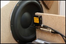
What if Vituix could import the real cone excursion data into the enclosure tool design alongside the box measurements ? ARTA has this feature, but it would be nice if Vituix also had it, that way VituixCAD would be a fully fledged platform. Its just a thought.
The image show the general method, but I do not recommend doing both measurements at the same time due to obvious reflection issues from the construction.
Oneminde
Maybe this has been covered before, but if not, then perhaps it can create some interest.
What if Vituix could import the real cone excursion data into the enclosure tool design alongside the box measurements ? ARTA has this feature, but it would be nice if Vituix also had it, that way VituixCAD would be a fully fledged platform. Its just a thought.
The image show the general method, but I do not recommend doing both measurements at the same time due to obvious reflection issues from the construction.
Oneminde
Attachments
While I would be for a feature like that, as I have the laser needed. But I would think that this would be a very niche feature. I do not think it's very common to have this equipment among hobby users.
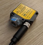
I searched Ebay every now and then for suitable laser for years and then in end got one for about 120EUR if I remember correct. That I thought was acceptable investment to satisfy the curiosity. As new these things go for >1kEUR and also as used they are usually much more expensive.
The setup issue I solved by hot gluing a nut to it, so I can attach it to the T beam of microphone stand directly.
Attachments
About a radial horn...
Measurement instructions should cover all radiator types, so this is mostly repeating the same information.
Specifying rotation center of polar measurement sequence might have subjective part if radiator does not have exactly known and mechanically measurable main axis direction. Usually rotation center is "on mouth level to main axis direction" with horns, and "on baffle surface at the center point of radiating area" with direct radiators such as cones, domes and planars. On frame surface if driver is naked.
VituixCAD is able to use measurement data in two planes only, typically horizontal and vertical. Azimuth angles are interpolated by the program if hor and ver are measured and user rotates simulated planes.
Rotation center must be common for hor and ver measurements so "ver 0 deg" will not be loaded and "hor 0 deg" represents axial response in the simulation.
Response filenames should (must in practice) have keyword for plane, typically "hor" for horizontal and "ver" for vertical plane. Plane keyword is usually before angle value.
Off-axis angle in degrees is integer value multiplied by 1, 10, 100 or 1000. Minimum angle range for full space simulation is 0...+180 deg in single plane. Maximum for full space is hor -179...+180 deg and ver -179...+179 deg. Mirror missing should be checked in practice (I'll probably remove the checkbox in the future).
Angle step could be 1 deg, but typically 10 deg is adequate at least for cones and domes. Horns may need smaller step e.g. 5 deg within listening window due to random reflections and resonances. Angle step can variate e.g. smaller to front and bigger to rear with unidirectional speakers.
If negative horizontal angles are acoustically equal to positive horizontal angles (axisymmetrical in hor plane), no need to measure and load negative hor angles.
If vertical angles equal to horizontal angles (circular or square radiator), no need to measure and load vertical plane at all.
If negative vertical angles equal to positive vertical, no need to measure and load negative vertical.
X,Y,Z coordinates of each driver instance in crossover schematic represent rotation center of DUT while off-axis measurement sequence. Driver position is relative to speaker origin which is usually perpendicular point of listening axis on baffle surface.
All measurements of the same driver must have common timing reference (usually at rotation center) so single channel measurements and minimum phase extraction are absolutely forbidden. Different drivers could have different timing reference, but common reference for all drivers i.e. all measurements is easiest to handle in practice.
An externally hosted image should be here but it was not working when we last tested it.
An externally hosted image should be here but it was not working when we last tested it.
---
This is practical standard for producing measurement data for XO simulation. Not specific for VituixCAD. For example LspCAD uses the same system for locating drivers with measurement data into simulation.
Last edited:
Its not part of the average diya dude, you are right about that. But for someone who is going to work on fairly complex cabinet constructions where multiple data points must be taken into considerations, it needs to be part of the equipmentWhile I would be for a feature like that, as I have the laser needed. But I would think that this would be a very niche feature. I do not think it's very common to have this equipment among hobby users.
I searched Ebay every now and then for suitable laser for years and then in end got one for about 120EUR if I remember correct. That I thought was acceptable investment to satisfy the curiosity. As new these things go for >1kEUR and also as used they are usually much more expensive.
")
Last edited:

^That looks Bandpass type 1; drivers in internal sealed volume and output from acoustical low-pass chamber with short vent. Combined sealed volume for two drivers is sum of upper and lower boxes. That will be Box Rear 1 in VCAD. Output section in the middle will be Box Front 2 and Vent Front 2 in VCAD.
^That looks Bandpass type 1; drivers in internal sealed volume and output from acoustical low-pass chamber with short vent. Combined sealed volume for two drivers is sum of upper and lower boxes. That will be Box Rear 1 in VCAD. Output section in the middle will be Box Front 2 and Vent Front 2 in VCAD.
Indeed, I used bandpass T1 for the lower boomer, and bandpass T3 with the smallest possible front event for the upper boomer, but i have no idea how to sum the upper and lower box. So noobie...
No there is no direct shortcut under the components, as the recalculation is automatically redone (correctly) after a second mouse click on another component. Also, when I remove a component, the graphs show a previous state, which is not calculated, or wrongly. A second click on another component and the graphs are updated correctly.
I don't get it. Why would it recompute correctly only after a mouse click instead of after doing ctrl+S ?That's not VituixCAD

Anyway, I have another question. If all the data I have of a speaker are the Thiele/Small parameters, I understand that the Enclosure tool can compute a theoretical frequency response SPL.txt and impedance response impedance.txt for that speaker with the enclosure I designed for it. Then I can export and import the generated files in the main simulator where I've drawn a crossover circuit.
My question is, when I generate these files in the Enclosure tool, must I check the "crossover of driver" checkbox or leave it alone ? I believe I shouldn't check it because then the exported data takes into account the existing crossover, which we don't want when importing the txt files in the main tool. Am I right ?
^Have you tried shorting via context menu (right click)? That is native function in the program. Ctrl+S is more like remote control which uses functions of context menu.
'Crossover of driver' is for those who need to check excursion and power consumption of sub-woofer with some bass shelf filter such as Linkwitz Transform. That should be unchecked for standard purposes such as simulating woofer's response in some cabinet.
P.S. Exporting response from Enclosure tool to XO simulation is not recommended. Short version of correct procedure is 'Checklist for designing a loudspeaker' starting on page 4 in user manual.
^Have you tried shorting via context menu (right click)? That is native function in the program. Ctrl+S is more like remote control which uses functions of context menu.
'Crossover of driver' is for those who need to check excursion and power consumption of sub-woofer with some bass shelf filter such as Linkwitz Transform. That should be unchecked for standard purposes such as simulating woofer's response in some cabinet.
P.S. Exporting response from Enclosure tool to XO simulation is not recommended. Short version of correct procedure is 'Checklist for designing a loudspeaker' starting on page 4 in user manual.
Yes I understand that, but I'm not designing a loudspeaker. I have a 25 year old pair of KEF 105/3, and I want to recap the Xover, because I believe the original electrolytic caps are cooked. However the Xover schematics is over complicated (the 105/3 is a 4 way speaker) and the original cap values were chosen by KEF with a 1% tolerance. I don't understand these companies go to such trouble to end up putting electrolytics in the Xover of their high end speakers.
Anyway, what I want to do is simulate the effect of a change of 5% in capacitor values and see which caps must be as close to the originals and which ones should be fine with a 5% change of value. But right now, I am a bit at a loss, because I reproduced the schema in Vituix, and the result doesn't resemble much like anything real.
^Simulating radiators' impedance and possibly acoustical response too is the worst option to choose imo.
Caps with 5% tolerance are probably close to 1% in practice so you can buy a set and verify C by measuring. If some individual is "too" bad, buy another. In addition, effect of capacitor type could have audible effect. Accuracy of C value is not necessarily the most significant factor with caps.
Second option is to measure impedance responses of drivers in place. Then simulate XO and effect of tolerance by monitoring transfer function of crossover at terminals of each driver from Filter graph. No need to load acoustical responses for drivers.
Real DIY approach would be redesigning whole XO by measuring all drivers and so on.
Yeah, I wish I could do a whole redesign of the XO, but my competence is really limited to soldering new caps in place of old ones (and using a LCR meter).^Simulating radiators' impedance and possibly acoustical response too is the worst option to choose imo.
Caps with 5% tolerance are probably close to 1% in practice so you can buy a set and verify C by measuring. If some individual is "too" bad, buy another. In addition, effect of capacitor type could have audible effect. Accuracy of C value is not necessarily the most significant factor with caps.
Second option is to measure impedance responses of drivers in place. Then simulate XO and effect of tolerance by monitoring transfer function of crossover at terminals of each driver from Filter graph. No need to load acoustical responses for drivers.
Real DIY approach would be redesigning whole XO by measuring all drivers and so on.
I really don't see myself doing the whole business especially on a 4 way speaker. There are way too many ways to screw up for someone with no experience like me. And since KEF no longer has replacement drivers for these speakers, there is no room for screwing up.
I agree that electrolytics suck and 23 in a crossover must suck the life of music.

Unfortunately, the cap values are high (lowest value is 7uF) and there isn't much space (this whole mids/tweeter board is about 20 cm side), so I can only see a couple of film caps for the tweeter and that's about it.
Hopefully, a full recap with brand new electrolytics will make the speakers sound better, because right now, I am rather underwhelmed by the sound especially in the mids and highs.
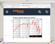
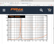
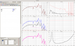
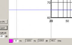
...I did some traces and the frequency looks to be off.
Looks be a little user mistake in that there's a mitchmatch in line point are set or locked at 20Hz but input number are set to a deviating 10Hz number : )
Attachments
- Home
- Design & Build
- Software Tools
- VituixCAD