First I have to say Thank you Kimmo for your excellent software, while the learning curve is a little steep, I have learned so much about acoustics and speaker design just by tinkering with the software. Anyway, I have spent weeks trying to figure out how to incorporate the enclosure tool frequency output into the main window without luck. It is my current understanding that this function is not available because this is not the purpose of the tool. please correct me if that is not correct.
My question then is how do we account for the effects of the enclosure when making the crossover. surely if I design for a flat response with either infinite baffle data or manufacturer data and then put it in a ported enclosure I will have a huge hump in the low end, no?
I see earlier threads that the enclosure tool is used in the early parts of the project to select drivers while the crossover design is left for the end. I see you suggest measuring the speaker in the enclosure and then use that which then includes the effect of the enclosure. This is fine for drivers I already have but I would like to use the software to prototype the speaker before I buy the drivers. is this a valid use of this software.
Finally the diffraction tool confuses me a bit because my understanding of it is that this is used to account for you baffle step correction. However if I have to have the drivers in an enclosure already shouldn't that be accounted for already in the measured data? what is the point of the diffraction tool if you cannot add the effects of the enclosure before you build it. Wouldn't the added bass response from the enclosure partially negate the baffle step losses?
I tried playing around with the calculator tools to add the responses but that does not seem to work and i cant find a good tutorial for such a function.
clearly i am missing some crucial point but despite going over the manual and tutorials I am not getting it. Please be kind to this newbie, any answers, advice, or links would be much appreciated. Also i am sorry if this has been fully explained somewhere before but I am not able to find it. Again thanks for all the hard work and I just wanted to say I never dreamed I could do this myself but this program (and this forum) make it very approachable.
You have to build the cabinet and measure the drivers (individually), import the data and then play with the crossover tool. The response and impedance will change when they are mounted in a cabinet, so, the best thing you can do is simulate or calculate the optimum cabinet size, do all the magic you can think off in order to make the cabinet as good as possible BEFORE you start adjusting with filters... yes, filters.My question then is how do we account for the effects of the enclosure when making the crossover. surely if I design for a flat response with either infinite baffle data or manufacturer data and then put it in a ported enclosure I will have a huge hump in the low end, no?
 You'll probably end up testing several since a response alone cannot tell you if its good or not, only your ears will.
Etaoin314 et al.
Crossover simulation uses far field frequency responses and impedance responses. It simulates just crossover network electrically, and calculates acoustical magnitude and phase changes per driver instance in XO due to distance difference compared to orbit at listening distance set in Options window. That's it.
You can produce far field frequency response data and impedance data by:
- measuring actual drivers in actual baffle/enclosure - prototype or final
- simulating theoretical drivers in theoretical baffle/enclosure
- almost any mix of previous two.
Professionals have prototype shop and anechoic so they can build prototype or final cabinet and measure at ~2.5 meters, skip some simulations, near field measurements and conversion to far field with diffraction simulation.
Recommended procedure for home indoors (without anechoic or large free space) designer such as myself is written in user manual, section "Checklist for designing a loudspeaker", pages 4-5. More detailed instructions can be found further. For example Diffraction and Merger tools are needed to convert near field measurements to far field off-axis responses (to full space).
Few examples if that procedure is not strictly followed:
* Enclosure and Diffraction tools are needed to simulate driver+enclosure system to full space, producing off-axis responses (hor&ver -179...+180 deg) and impedance response.
* SPL Trace and Diffraction tool are needed to create directivity data i.e. far field off-axis responses (to full space) for half space response curve in manufacturer's datasheet.
* Near field measurements, Merger and Diffraction tools are needed to create directivity data i.e. far field off-axis responses (to full space) if directivity data of time-windowed far field measurements is not reliable at low frequencies.
Main reason why main program does not have any acoustical simulations is that accurate simulation is not available for all radiators. For example resistance enclosure and cone directivity are so complex that solving of parameters required for accurate simulation is more difficult and slower than making measurement from actual device in prototype baffle/box. Interface to XO design with far field frequency and impedance responses is versatile, simple and as accurate as your data.
Hi,
Thank you Kimmosto for such an extraordinary piece of software. I really admire your work.
I am preparing measurements and was searching thread in order to fully understand manual and measurements preparations as far as measuring drivers mounted on tilted baffle with tweeter in a waveguide and enetering right data to the program are concerned.
I have come across your talk with InOtIn and one thing got me confused in your explanation of applying Z values to the program concerning example speaker. Shouldn't the Z value of the tweeter be little positive (not negative) if 12M is the origin?
In order to make matters clear I prepared three pictures that explain what I understood so far. Please correct me if I am wrong.


Red vertical line represens rotation axis.
I enter xyz to the program as location of the driver.
I enter waveguide depth as delay of the driver in us.
Is that correct?
Thank you.
Bartosz
Thank you Kimmosto for such an extraordinary piece of software. I really admire your work.
I am preparing measurements and was searching thread in order to fully understand manual and measurements preparations as far as measuring drivers mounted on tilted baffle with tweeter in a waveguide and enetering right data to the program are concerned.
I have come across your talk with InOtIn and one thing got me confused in your explanation of applying Z values to the program concerning example speaker. Shouldn't the Z value of the tweeter be little positive (not negative) if 12M is the origin?
In order to make matters clear I prepared three pictures that explain what I understood so far. Please correct me if I am wrong.
Red vertical line represens rotation axis.
I enter xyz to the program as location of the driver.
I enter waveguide depth as delay of the driver in us.
Is that correct?
Thank you.
Bartosz
Simulator does not think - it just calculates by measurement data you load and parameters you enter
In that particular case all drivers have common X=0mm and R=0deg but close to everything else is individual per driver.
Tweeter: Z and T are small negative values.
Small mid 12M: Could be origin (=endpoint of design axis) so Z=0mm and T=0deg.
Big mid 18W: Z is small negative and T is small positive.
Woofers have common negative Z (bigger than previous Zs) and T=0deg.
Y of each driver is relative to small mid which was selected as origin.
This is not very simple but enables mechanical adjustments with X,Y,Z,R,T parameters with simulator as well as combining whole construction from different prototypes for each driver (accepting some error in inter-diffraction/scattering/reflection).
Hi Kimmo:
Someone on another forum posed the question as to whether the Dayton PT-mini planar tweeter would work well in a line array. I then did a 5 minute simulation with your diffraction tool and the results were somewhat negative. This wasn't terribly surprising as the gap between radiators in the array is approximately 38% of the pitch, nowhere near the 10% rule of thumb developed mathematically. As I modify the sim model to display results for an ever taller driver at the same step, the results improve until at/around 10% things start looking really good. By "good" I mean I don't see combing effects or similar anomalies until above 16 khz.
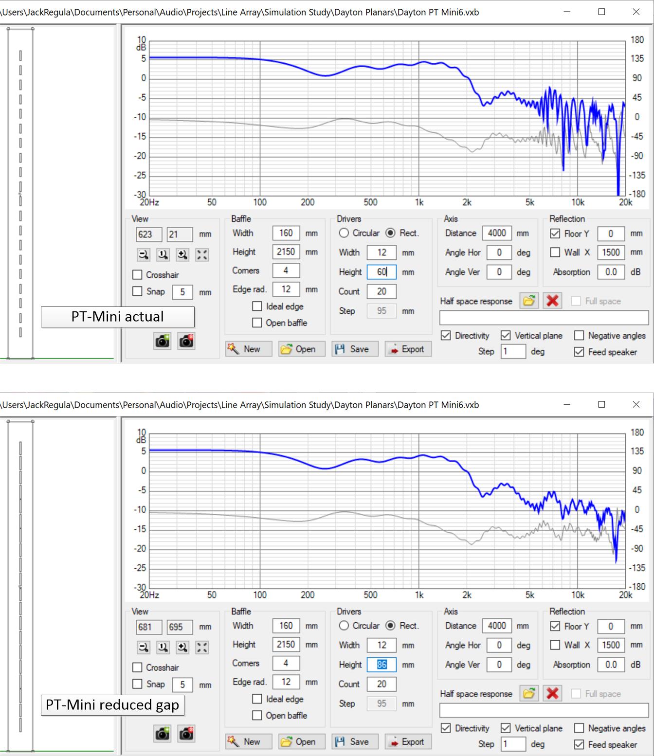
The question came up as to what extent these results could be trusted. I have confidence in Vituix based on my experience with a circular piston line array. But does that apply to a high aspect ratio rectangular device? In the one case you have a continuous line source approximated by closely spaced discrete drivers; in the other case you have a continuous line source with gaps, which get different mathematical treatments. But given the results of my progression of simulations, I think these specific results might indeed be valid.
My experience with it tells me to trust Vituix. But is that trust merited for the special case of a high aspect ratio driver in a line array? (Who better to ask than you?) Do you use a different computation methodology for rectangular vs circular drivers?
Thanks,
Jack
Someone on another forum posed the question as to whether the Dayton PT-mini planar tweeter would work well in a line array. I then did a 5 minute simulation with your diffraction tool and the results were somewhat negative. This wasn't terribly surprising as the gap between radiators in the array is approximately 38% of the pitch, nowhere near the 10% rule of thumb developed mathematically. As I modify the sim model to display results for an ever taller driver at the same step, the results improve until at/around 10% things start looking really good. By "good" I mean I don't see combing effects or similar anomalies until above 16 khz.
The question came up as to what extent these results could be trusted. I have confidence in Vituix based on my experience with a circular piston line array. But does that apply to a high aspect ratio rectangular device? In the one case you have a continuous line source approximated by closely spaced discrete drivers; in the other case you have a continuous line source with gaps, which get different mathematical treatments. But given the results of my progression of simulations, I think these specific results might indeed be valid.
My experience with it tells me to trust Vituix. But is that trust merited for the special case of a high aspect ratio driver in a line array? (Who better to ask than you?) Do you use a different computation methodology for rectangular vs circular drivers?
Thanks,
Jack
Attachments
I'm still waiting problematic file(s) to my e-mail... Or is this already solved?
........
Few possible reasons if response will not show up:
- file is bad
- some extrapolation problem
- impedance response is zero or impedance Scaling is 0 i.e. driver is electrically close to short circuit (~10 mOhms)
- file naming rules are not followed -> response to initially selected reference angle does not exist -> response is not updated to chart
Thank you both for your prompt response and especially Kimmo for his amazing software and support!
I had already some good results but I look forward to my holidays next week to conclude and send you more precise feedback and may be some problematic files if it will not be fully solved.
...measuring drivers mounted on tilted baffle...
This is mentioned in 'Measurement preparations' document, but unfortunately very shortly: "Turn speaker back/front if front baffle is tilted."
Each driver is measured at 1000 mm from center point of driver on baffle surface. Measurement axis (mic - driver) is perpendicular to baffle surface for that particular driver. This rule is valid while you're capturing response data.
Location, rotation and tilt parameters (X,Y,Z,R,T) of each driver instance in crossover are set so that simulation matches with reality. In your case all drivers have T=+3 deg (nose up = positive). If you have selected mid as speaker's origin (XYZ=0,0,0mm ~ ear is at mid's elevation while listening), tweeter's Z=+8mm, mid's Z=0mm and woofer's Z=-28mm per your images.
I enter waveguide depth as delay of the driver in us. Is that correct?
NO, if you are using dual channel measurement connection and mode and frequency responses are exported with Reference time common for all far field measurements - how advised in 'Measurement preparations' document. Delay correction for all drivers is 0 us in that case because difference in acoustic centers compared to driver's origin (=rotation center) is included in measured phase response, and valid to all measured off-axis directions.
But if you are using USB mic or otherwise measure in single channel mode and phase responses are derived with minimum phase calculation, you have to solve difference in acoustic centers (perpendicular with front baffle) and enter as Delay [us] (not to Z mm which would cause timing error to off-axis with unidirectional drivers). But that is not recommended method due to several possible error sources.
But does that apply to a high aspect ratio rectangular device?
...
But is that trust merited for the special case of a high aspect ratio driver in a line array? (Who better to ask than you?) Do you use a different computation methodology for rectangular vs circular drivers?
We can be confident that there's always error in simulations
Off-axis responses of individual circular pistons and rectangular planars are calculated to infinite distance. Not to axial distance adjusted by user. Error probably increases with large/high radiators because axis distance to surface size ratio decreases. User manual recommends to simulate long planars with multiple smaller planars with zero gap (end of page 44), but that's not binding. User to test and make final decision.
Off-axis response of circular piston is calculated with BesselJ1, and rectangular planar with sinc function. Difference is easy to visualize with Calculator tool, for example width=100mm vs. diameter=120mm.
Ok.
In order to take measurements of a tiled loudspeaker. The speaker needs to be tilted so that it's baffle is perpendicular to floor surface (or you can play with mic).
Is that correct?

In order to take measurements of a tiled loudspeaker. The speaker needs to be tilted so that it's baffle is perpendicular to floor surface (or you can play with mic).
Is that correct?
This is mentioned in 'Measurement preparations' document, but unfortunately very shortly: "Turn speaker back/front if front baffle is tilted."
Each driver is measured at 1000 mm from center point of driver on baffle surface. Measurement axis (mic - driver) is perpendicular to baffle surface for that particular driver. This rule is valid while you're capturing response data.
.
^That's correct.
Some compromise workaround is needed if speaker is too heavy or complex for tilting. Few degrees tilt while measurement is not so critical with ordinary dome/cone drivers. More important is that rotation center stays at the center point of driver on baffle surface. That enables setting of actual driver locations into simulator and reduces data overflow from time window while converting IR to FR with constant Reference time.
For example measuring of small 2-way with small circular drivers is okay at common elevation; average Y of W and T. That produces about 4 deg tilt error to both drivers at 1 meter, but makes things a bit easier because no need to move the mic.
Ok, thank you. I get it. This approach indeed makes sense, program has freaquency response of each driver in a box 0 degrees. In comparison to talking measurements with only one position of mic at 1 meter program has more data. Making baffle perpendicular to floor surface makes it easier to maintain the rotation center.
^That's correct.
Some compromise workaround is needed if speaker is too heavy or complex for tilting. Few degrees tilt while measurement is not so critical with ordinary dome/cone drivers. More important is that rotation center stays at the center point of driver on baffle surface. That enables setting of actual driver locations into simulator and reduces data overflow from time window while converting IR to FR with constant Reference time.
For example measuring of small 2-way with small circular drivers is okay at common elevation; average Y of W and T. That produces about 4 deg tilt error to both drivers at 1 meter, but makes things a bit easier because no need to move the mic.
Rev. 2.0.18.5 (2019-06-18)
* Added svg file support to Export image of charts.
Note! Polarmap should not be exported as svg due to excessive file size and missing contour line support.
* Added svg file support to Export image of charts.
Note! Polarmap should not be exported as svg due to excessive file size and missing contour line support.
^Q1: How many off-axis responses you have measured and loaded for the drivers?
Q2: Do all drivers listed in Drivers have frequency responses to the same off-axis angles?
Q3: Is plane and off-axis angle coded properly in response filenames?
Q4: Does angle decoding rules in Options window match with file names?
Q5: Are all drivers connected with XO to generator and components not Open or not shorted to ground and impedance scaling ~1.0?
Q6: Is Mirror missing checked in Options?
Q7: Have you downloaded and studied sample projects Kontiainen and Epe-3W? If yes, what features/settings are different in your project? Those were measured with CLIO so angle values are multiplied by 100.
Svg export of polarmap improved to the latest build few minutes ago. Contour lines are not added but otherwise okay. Background is not filled with solid white.
Svg rendering is not perfect in all browsers due to some rounding issue. IE 11 works fine but Firefox 67 (64-bit) and Chrome not so good.
An externally hosted image should be here but it was not working when we last tested it.
.svg)
Svg rendering is not perfect in all browsers due to some rounding issue. IE 11 works fine but Firefox 67 (64-bit) and Chrome not so good.
Last edited:
Rev. 2.0.18.6 (2019-06-22)
* Added contour line support to svg export of polarmap. Polarmap recommended to export as png due to smaller file size and rendering speed.
* Added contour line support to svg export of polarmap. Polarmap recommended to export as png due to smaller file size and rendering speed.
Rev. 2.0.18.7 (2019-06-26)
* Added svg file support to Export image of crossover schematic.
* Fixed polarmap color blending with short angle range < 360 deg or < 180 deg with half space checked. Bug since 2.0.18.6 (2019-06-22).
* Added svg file support to Export image of crossover schematic.
* Fixed polarmap color blending with short angle range < 360 deg or < 180 deg with half space checked. Bug since 2.0.18.6 (2019-06-22).
Last edited:
- Home
- Design & Build
- Software Tools
- VituixCAD