^Lime green in SPL chart is minimum phase response calculated by total magnitude response to reference angle (black in SPL and Power&DI charts).
If you're also asking what is "minimum phase response", it's equivalent to phase response of full range radiator without crossover with constant acoustic center at all frequencies. But it's just calculated approximation with few assumptions such as automatic slope extensions at LF and HF outside measured range.
If you're also asking what is "minimum phase response", it's equivalent to phase response of full range radiator without crossover with constant acoustic center at all frequencies. But it's just calculated approximation with few assumptions such as automatic slope extensions at LF and HF outside measured range.
Additions to the latest build of rev. 2.0.18.1 (2019-05-21)
Main program
* Vertical scrollbar of crossover schematic restored. Was accidentally hidden since rev. 2.0.15.0.
* First item in Drivers list box in Optimizer window initially selected to enable 'Axial response of Driver' and 'Filter gain of Driver' radio buttons before driver selection by user. Also word order in user manual fixed.
SPL / Impedance matching
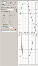
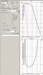
Hi, just a question on how the 'crossover of current driver' and 'feed speaker' boxes are meant to work.
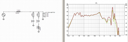
Just for a test I've made a single-driver subwoofer and taken some screenshots (attached).
First I calculate my impedance-matching RC and RLC networks for the driver in free space in the main window, then add in a single coil for a first-order LPF (it ain't great nor realistic, but it's good enough for now).
So that's fine, the impedance, filter, and SPL plots change in realtime as I tweak values.
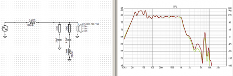
Now I open the Enclosure Tool, and select 'Crossover of Driver'. The SPL graph (in the Enclosure window) changes to account for my LPF coil, which is good.
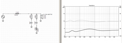
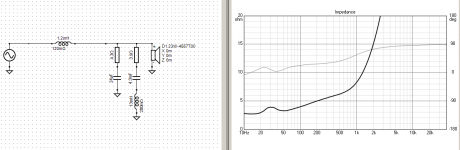
The impedance graph (in the Enclosure window) changes depending on whether I choose closed or vented, but tweaking the values of my RC and RLC circuits does nothing.
Neither does the single-peak of closed, or double-peak of vented, impedance spikes translate back into the main window.
Changing the values of my LPF coil makes the SPL graph in the Enclosure Tool window to change, which is good.
Changing the enclosure type or tweaking box/vent sizes also makes the SPL graph in the Enclosure Tool window change.
But this doesn't then feed back into the SPL response in the Main Window (neither with 'feed speaker' checked nor unchecked).
In short, I want to do 2 things.
1: compensate impedance of the driver in the box, not just driver in free space.
2: see overall response of driver-in-box, not just response of driver in freespace and theoretical box-response separately.
How do I do these in real time? Do I have to do something like export and merge or something each time I make a change?
Hi, just a question on how the 'crossover of current driver' and 'feed speaker' boxes are meant to work.
Just for a test I've made a single-driver subwoofer and taken some screenshots (attached).
First I calculate my impedance-matching RC and RLC networks for the driver in free space in the main window, then add in a single coil for a first-order LPF (it ain't great nor realistic, but it's good enough for now).
So that's fine, the impedance, filter, and SPL plots change in realtime as I tweak values.
Now I open the Enclosure Tool, and select 'Crossover of Driver'. The SPL graph (in the Enclosure window) changes to account for my LPF coil, which is good.
The impedance graph (in the Enclosure window) changes depending on whether I choose closed or vented, but tweaking the values of my RC and RLC circuits does nothing.
Neither does the single-peak of closed, or double-peak of vented, impedance spikes translate back into the main window.
Changing the values of my LPF coil makes the SPL graph in the Enclosure Tool window to change, which is good.
Changing the enclosure type or tweaking box/vent sizes also makes the SPL graph in the Enclosure Tool window change.
But this doesn't then feed back into the SPL response in the Main Window (neither with 'feed speaker' checked nor unchecked).
In short, I want to do 2 things.
1: compensate impedance of the driver in the box, not just driver in free space.
2: see overall response of driver-in-box, not just response of driver in freespace and theoretical box-response separately.
How do I do these in real time? Do I have to do something like export and merge or something each time I make a change?
Attachments
Hi, just a question on how the 'crossover of current driver' and 'feed speaker' boxes are meant to work.
It is meant for checking excursion and power requirement with active crossover with some bass boost filtering such as Linkwitz Transform or Peaking EQ.
This feature is not so important with passive crossover because those parameters can be checked without crossover, and box dimensioning with Enclosure tool is done way before measurements and crossover designing with the main program. Recommended design procedure is visible in user manual, section "Checklist for designing a loudspeaker" beginning on page 4. Working with Enclosure tool is items #3...#4, and designing crossover with the main program is items #17...#24, probably few weeks later.
BUT if someone is willing to play with combination of simulated driver+enclosure system and passive crossover, impedance response should be fed from Enclosure tool to driver selected in Drivers tab of main program manually every time when impedance curve changes by checking Feed speaker, clicking Impedance button, and so on. So feeding impedance response back to main program is NOT yet automatic function such as feeding filter transfer function from crossover to Enclosure tool.
Last edited:
feeding impedance response back to main program is NOT yet automatic function
Workaround done for direct ZR link from Enclosure to main. This is probably just confusing cheap trick, but allows e.g. enclosure adjustment without repeated manual exporting of impedance response to main program as txt/zma file. Not recommended method for daily use, but available for some special needs.
Rev. 2.0.18.2 (2019-05-24)
Enclosure
* Impedance response is copied from Enclosure tool to selected driver in the main program if 'Crossover of driver' is checked in Align tab. Copied response is temporary in memory until impedance response is read from file again, for example due to scaling.
^Best to send file as wav and human readable text exported with Fuzz to me by e-mail for investigations. Wav reader in VCAD is quite new and it has few restrictions e.g. number of channels. Supported formats should be mono or stereo (=max 2 channels) 16-bit PCM, 32-bit PCM, 32-bit IEEE, 64-bit PCM and 64-bit IEEE.
Dropbox link shared with WAV, CSV export of IR, FRD export, and screenshot to show how FM4.2.2 processes these data into IR and FR plots.
For some reason the IR CSV export is ginormous (almost 24MB, or 8x larger than the WAV it came from) and I can't get FM to start the export at a reasonable time. So I doubt that's useful.
For some reason the IR CSV export is ginormous (almost 24MB, or 8x larger than the WAV it came from) and I can't get FM to start the export at a reasonable time. So I doubt that's useful.
^Wav files by FuzzMeasure should work with these additions:
Rev. 2.0.18.3 (2019-05-27)
Convert IR to FR
* Added support for 24-bit PCM wav.
* Added support for non-standard Apple wav with FLLR chunk.
Rev. 2.0.18.3 (2019-05-27)
Convert IR to FR
* Added support for 24-bit PCM wav.
* Added support for non-standard Apple wav with FLLR chunk.
Hi Kimmo,
Any chance that you might be able to add to the Options Menu a Y axis control for SpL similar to that of the Filter Y axis menu Option? This would allow for scrolling up and down the SpL range but might allow the secondary Y axis for Phase to be adjusted without it looking strange.
Thanks so much,
Jay
graph to copy to clipboard?
Copying to clipboard is integrated to Export image and Export six-pack commands. You can accept copying after exporting to some dummy png file. Not so easy and fast as direct copy but exists. This is done as workaround to avoid double menu items in everywhere.
Y axis control for SpL similar to that of the Filter Y axis menu Option?
Automatic maximum is much better than manually adjusted in my opinion. Manual Y max is almost pain in the a** where exists (including max filter gain controlled via Options window).
Curves with minimum = 0 are typical exceptions. We might be interested in some details close to 0 rather than close to maximum.
It's certain that manual adjustment of SPL max cannot be the only option. It would need some automation or auto scale command which is able to override manual setting in case everything is hidden somewhere below or above visible range after some major change.
^Wav files by FuzzMeasure should work with these additions:
Rev. 2.0.18.3 (2019-05-27)
Convert IR to FR
* Added support for 24-bit PCM wav.
* Added support for non-standard Apple wav with FLLR chunk.
Incredible, thanks! I'm now able to see the IR , window it, and export it into a readable text file that makes sense. I'll still having some issues getting my exports to show up in the main program screen (adding a 100dB offset so the average SPL is ~75dB with my mike cal file), but I suspect that's just part of my learning curve.
adding a 100dB offset so the average SPL is ~75dB with my mike cal file
PCM wav is normalized while reading due to integer data type so that is not the best choice for transferring pressure (SPL), voltage, impedance etc. values from measurement programs or other applications.
IEEE wav is read "as is" without value manipulation. So that is much better format for IR files - if available in measurement program and measurement program does not normalize/force values e.g. within -1.0...+1.0 which is common with audio files.
I'll still having some issues getting my exports to show up in the main program screen...but I suspect that's just part of my learning curve.
That was accurate: I hadn’t connected the driver to the amp in the crossover pane.
Also, as mentioned above no offset.
Copying to clipboard is integrated to Export image and Export six-pack commands. You can accept copying after exporting to some dummy png file. Not so easy and fast as direct copy but exists. This is done as workaround to avoid double menu items in everywhere.
Thanks Kimmo. I see it now.
Jay
I see it now.
Rev. 2.0.18.4 (2019-05-28)
* Copy and export commands are separated in context menus.
* Exporting of schematic image moved from File->Export to context menu of crossover.
This was quite big job but exporting of dummy files for copy wasn't so motivating.
Rev. 2.0.18.4 (2019-05-28)
* Copy and export commands are separated in context menus.
* Exporting of schematic image moved from File->Export to context menu of crossover.
This was quite big job but exporting of dummy files for copy wasn't so motivating.
Thank you very much Kimmo. I make up reports with lots of graphics and measurements on all projects both during and after they are done. This saves some time.
Jay
Y axis control for SpL similar to that of the Filter Y axis menu Option?
I can consider some combination of automatic and manual adjustments for Ymax of charts. Few users have proposed manual Ymax and/or scale locking but that is out of question because for example SPL max could change >100 dB when project changes or scale of measurements or gain of buffers is radically adjusted.
Current method for SPL max is automatic with ~2 dB hysteresis preventing continuous jumping while small adjustments just below major grid. I have history with LspCAD having auto Ymax so quite difficult to find a single good reason for manual tweaking
")
- Home
- Design & Build
- Software Tools
- VituixCAD