but you both missed my point. I'm simulating a ground plane CBT that makes use of the floor reflection to double the effective size of the array. I thought it would be interesting to see if that could be simulated simply by checking the include box. The crossover schematic gets really busy when I include the 24 ground image drivers in it.
Yes normally I would never do that except for a quick look at where the first null fell.
Yes normally I would never do that except for a quick look at where the first null fell.
Last edited:
but you both missed my point.
I don't think so. I would ignore mirror sources and floor gain also with CBT. At least initially with the first design until significance and compatibility with room geometry, acoustics and location possibilities are evaluated also by listening.
PS. Except that it's not probable that I would design CBT or any other line array
")
I may have a bit bad attitude to excursion simulation because that's something we can't increase. Just try to make some workarounds if "adequate" volume excursion capacity is not an option. For example cut sub frequencies or compress with small sealed. In addition, useful excursion could be much different than mathematical Xmax so value of simulation only could be low.
Everything you say is true, except
I want to do an excursion simulation up front, before I choose drivers etc so I don't get into a situation where I find I don't have enough volume displacement to hit my target SPL and have to build another prototype with more or bigger drivers
I don't think so. I would ignore mirror sources and floor gain also with CBT. At least initially with the first design until significance and compatibility with room geometry, acoustics and location possibilities are evaluated also by listening.
PS. Except that it's not probable that I would design CBT or any other line array
I've had both models running, with and w/o floor reflection and gain. I should contrast them but now they are out of sync with each other.
I'm more confident of the floor gain model because of Don Keele's analysis and because my house has a tile floor set on a concrete slab on ground as well as block exterior walls. My Synergy corner horn depended on corner gain and got it down to where the walls and floor became transparent, which was around 30-40 Hz. I think in this new house the floor ought to be reflective down much lower than that.
But what is your preferred speaker architecture? I chose CBT for small footprint plus seemingly easy room integration plus I've always been fascinated with line arrays.
..I'm simulating a ground plane CBT that makes use of the floor reflection to double the effective size of the array.
-what do you mean by that?
It's just a bounded condition right? Basically half-space for a Ground-plane CBT.
..if it's a distance/pressure thing (other than baffle effects), that seems more suited to post-processing in an array-calculator (..where you might just need to import each set of mid+tweet as separate speakers, align/stack in the desired arc, and then "combine" the array).
Last edited:
-what do you mean by that?
It's just a bounded condition right? Basically half-space for a Ground-plane CBT.
..if it's a distance/pressure thing (other than baffle effects), that seems more suited to post-processing in an array-calculator (..where you might just need to import each set of mid+tweet as separate speakers, align/stack in the desired arc, and then "combine" the array).
I think there is more to it than "just a boundary condition" but it is indeed the boundary condition that its based on and the reflections that make it work (that make a half arc CBT perform like a full arc) but the magic of the CBT comes from its curvature and weighting.
I'll link Keele's paper so you can judge for yourself. Keele argues that a half arc CBT curved array sitting on a perfectly reflective ground plane is equivalent to a full arc free standing array and then goes on to show calculated sound pressure diagrams that prove his case and compare CBT to other kinds of line arrays.
http://www.xlrtechs.com/dbkeele.com/PDF2/Keele%20(2005-10%20AES%20Preprint)%20-%20CBT%20Paper%205.pdf
OK, this is totally a distance/pressure thing, and what Keele is referencing in this instance is a (freq.) lower-limit for line source behaviour at a certain distance. ..and it's the same for a standard array.
Griffin's paper is actually much better for this topic than Keele's:
https://audioroundtable.com/misc/nflawp.pdf
Honestly the thing that Keele is trying for with the CBT is arguably a waste of time in a typical domestic setting: and that's how vertical directivity is affected with distance and a typical line source vs. a arc'ed shaded line source. Domestically it's pointless (CBT) vs. a long (typical 6+ feet) "straight" un-shaded line source relative to a typical ceiling height and distance from the speaker. In a commercial venue though it's a HUGE factor, but it was already a "known quantity" (..which is why there are numerous software programs on how to stack arrays).
-anyway, this is definitely in the category of "POST-PROCESSING" for room/venue effects and multi-listeners. It's not something I'd expect integrated into a home loudspeaker simulation program. If you want integration like this there is EASE which recently bundled their simulation program: EASE Speakerlab (similar to VituixCAD) into EASE itself.
Scroll down to see what I'm talking about:
EASE - SpeakerLab
Last edited:
All this does bring up something interesting though. (..to me anyway.)
-what about getting your sim INTO post-processing software.?
In this case I'm thinking it might be handy to DIRECTLY output a CLF (file) with your sim from VituixCAD. So that you can then input it into something like JBL's DDA. (..rather than have to send another file-type to CLF's reader/viewer for the conversion.)
Authoring CLF
Intellivox DDA Software
OK, this is totally a distance/pressure thing, and what Keele is referencing in this instance is a (freq.) lower-limit for line source behaviour at a certain distance. ..and it's the same for a standard array.
Griffin's paper is actually much better for this topic than Keele's:
https://audioroundtable.com/misc/nflawp.pdf
Honestly the thing that Keele is trying for with the CBT is arguably a waste of time in a typical domestic setting: and that's how vertical directivity is affected with distance and a typical line source vs. a arc'ed shaded line source. Domestically it's pointless (CBT) vs. a long (typical 6+ feet) "straight" un-shaded line source relative to a typical ceiling height and distance from the speaker. In a commercial venue though it's a HUGE factor, but it was already a "known quantity" (..which is why there are numerous software programs on how to stack arrays).
-anyway, this is definitely in the category of "POST-PROCESSING" for room/venue effects and multi-listeners. It's not something I'd expect integrated into a home loudspeaker simulation program. If you want integration like this there is EASE which recently bundled their simulation program: EASE Speakerlab (similar to VituixCAD) into EASE itself.
Scroll down to see what I'm talking about:
EASE - SpeakerLab
Hi Scott:
Thanks for those links.
I'm very familiar with JimG's paper. You might be interested to know that last year he designed and built a CBT, took it to RMAF, and won first prize!
My New Line Array--It's a Modified CBT24
To me and for my living room, CBT is an alternative to a staight line floor to ceiling line array. Both perform well. I prefer the CBT simply because it can be significantly smaller. I also suspect it may have less boundary interference but I'm not sure how much difference that will make.
Let me explain the latter. The wall reflections from a straight line array are relatively concentrated in time, spread only due to the height variation. Those from a curved array are also spread in time due to the front to back depth of the curve but less so due to height. The greater the spread, the broader and shallower any boundary nulls. This needs to be tested/quantified. Can the software you linked do this? I'm looking into it...
Jack
But what is your preferred speaker architecture?
OT
I don't have any particular favorite. Anything works in good room acoustics in practice. I have tried line arrays, horns, wave guides, small cardioids, tower cardioids and many standard 1...4 ways. Strongest directivity methods which try to beat bad room acoustics could increase the risk that lower quality drivers, concepts and mechanics are selected due to financial limit or physical features/limits related to selected directivity technology. In addition, standard technology could still sound better in good acoustics than very directive speaker in bad acoustics.
So room acoustics should be treated first to produce low and flat EDT. As low EDT as subjective preferences allow. Then you can choose any technology and focus to important quality measures other than just directivity.
About line arrays. I've never heard CBT, but it looks a bit better (though ineffective) concept than linear array which is not full length from floor to ceiling. Variable near to far field transition of linear array is quite annoying and difficult to handle with variable listening distance imo.
/OT
I appreciate that reply especially since its OT. I felt the same way about treatment but am limited by WAF so am trying to work with the room acoustics that I have, plus drapes, area rugs and padded furniture.
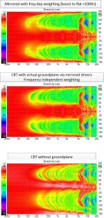
I suppose its also OT (apologies) but I'd like to show the attached on groundplane CBT directivity if for no other reason than to show off the power of Vituix.
These curves are from a 24 driver (2" piston), 36 degree CBT. Mirroring the drivers to approximate the ground plane response made a huge difference and directivity holds just about down to 100 Hz. The weighting/shading costs 3 db in SPL in excursion limited region and the 2" drivers are already a little bass shy. Trying to get this 3db back by essentially unshading below 100 Hz with first order PEQ causes vertical lobe to appear between 100 and 200 Hz. Perhaps this can be fixed with sharper roll off on the LF boost. Its awesome to be able to explore and optimize this before making any sawdust.
Attachments
Its awesome to be able to explore and optimize this before making any sawdust.
Maybe you are already aware that response data with 5 deg steps does not give very accurate vertical off-axis simulation with line arrays because frequency responses are not interpolated between measured/simulated angles. Delay/phase information is calculated by distance differences so that part in simulation is accurate, but program selects off-axis response from Drivers tab which is closest to angle between driver's axis and 3D line from center point of driver to mic/listening point.
We would need off-axis responses with 1 deg angle step to get the most accurate simulation VituixCAD could offer, but 360 off-axis responses (per plane) keeps program so busy that using becomes too inconvenient (though simulation result looks very nice). Minimum step in Diffraction tool is kept as 5 deg because simulated off-axis will not be accurate anyway.
I wasn't aware of that. But how accurate is "not very"?
And how accurate does it need to be at this stage where I have already decided on a CBT and I have to make choices about height of the array, number and kind of drivers. Even not very accurate might be good enough and would be better than nothing provided its not misleading.
I think I will compare sim results for 15, 10, 5 degree steps and see if there is a trend
I wasn't aware of that. But how accurate is "not very"?
And how accurate does it need to be at this stage where I have already decided on a CBT and I have to make choices about height of the array, number and kind of drivers. Even not very accurate might be good enough and would be better than nothing provided its not misleading.
I think I will compare sim results for 15, 10, 5 degree steps and see if there is a trend
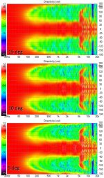
Here are plots with 5,10, 15 degree steps set in diffraction tool. They are all qualitatively the same. If I look closely. I can see differences in the yellow green transition regions. I imagine with 1 degree steps, we could see fine detail in these regions. I wouldn't mind waiting a few minutes for Vituix to crank out that level of detail when I felt I needed it. But I'd probably also want a cancel button for when I forgot to see the step size back to a normal 5 degrees
Attachments
Angle resolution of off-axis data and directivity difference between actual driver and ideal piston are the most obvious errors with simulated data. I could easily reduce minimum angle step of diffraction simulation down to 1 deg, but that would not reduce the other error a bit. This kind of simple simulation is inaccurate anyway, but hopefully gives some information about whole project before making any prototype for measurements.
With measured data we are able to reduce both errors (in addition to error in baffle diffraction simulation). Angle resolution could be 1 deg and off-axis data with actual driver - not just simple simulation with Bessel J1 function. No need to built whole array.
With measured data we are able to reduce both errors (in addition to error in baffle diffraction simulation). Angle resolution could be 1 deg and off-axis data with actual driver - not just simple simulation with Bessel J1 function. No need to built whole array.
"some info about the whole project before making any prototype" is all I'm looking for! I've got it and I should move on. Still working driver evals and tradeoffs though. Nice 1.5" full range driver that needs help from a woofer vs 2" or 2.5" drivers that get well into subwoofer territory on their own but aren't as smooth on top
Interesting - you suggest measuring single driver with this 1 degree measurement step size and linking that data into the sim instead of diffraction export. That is a lot easier than building and putting the entire CBT on a turntable but its still a lot of measurements for a DIYer. hmmm
Interesting - you suggest measuring single driver with this 1 degree measurement step size and linking that data into the sim instead of diffraction export. That is a lot easier than building and putting the entire CBT on a turntable but its still a lot of measurements for a DIYer. hmmm
you suggest measuring single driver with this 1 degree measurement step
I would measure with 5 deg step despite of some inaccuracy. 5 deg step allows merging of simulated LF directivity and measured HF directivity. That could be useful if directivity information of far field measurements is not logical and reliable enough at LF.
Motorized turntable would be helpful with 1 deg step
If you decide to measure with 1 deg step, load response data after crossover and driver locations are done. And clear measurement data temporarily if you need to make big change to crossover. Otherwise program jams quite badly.Enclosure tool does not follow the main program Options -> Frequency range setting. Would it be possible to enable that?
This feature is now restored to Enclosure tool, rev. 2.0.13.2 (2019-02-11). Also diffraction response is restored to Align tab (earlier in Directivity tab). Full space response is shown in SPL graph (in brown) if Diffraction response is checked.
No export for full space response. That should be exported with Diffraction tool where off-axis responses (to full space) are available too.
Don't want to derail this thread, did do some searching but came up empty. Let me know if there's a better place to post this.
The Vituix manual seems to indicate that the "ways" selection is the first step in speaker simulation, however when I open Vituix CAD, neither the 'Way" selection nor "Count & connect" input fields are present.
I have connected the generator to the driver with a single wire on the crossover schematic.
I have updated to the latest .NET version.
Any guidance on how to go about starting a simulation project would be greatly appreciated. Thanks!
"ways" ... "Count & connect" input fields are present.
"Way" is now heritage abstract term describing driver or driver group with common filter in crossover. Version 1.1 had/has way enabling and selection, but with version 2.0 you need to make the same by adding driver names and loading measurement data to Drivers tab, adding separate components, wires and drivers to crossover schematic, and finally linking measurement data to each driver instance in crossover with combo box just below schematic image. More complex but limitless.
Please follow items in How to start working with VituixCAD. Refresh page to see the latest. Investigating demo projects is important to get idea what typical (passive) project contains, how response file naming works and response data linked to drivers in crossover.
Crossover manipulation is presented in video VituixCAD 2 free form network
- Home
- Design & Build
- Software Tools
- VituixCAD