DC offset compensation in Convert IR to FR can be used to improve FR slopes at LF, but possibilities to improve normalized directivity graphs such as normalized polarmap and directivity estimation for Merger tool are close zero. Normalized graph could go even worse because DC compensation is also sensitive to LF noise; traffic, ventilation, construction etc. But if environment is silent and DC bias of soundcard is stable, this is very good option because IR window cannot be started very close to IR peak due to rotation and radiator diameters and different acoustical centers while off-axis measurement sequence. Variable starting point is too difficult if sequence includes tens of measurements.
An externally hosted image should be here but it was not working when we last tested it.
Last edited:
...when I do enclosure (bass alignment) simulations and add XO for the driver, it affects the response, but not the impedance.
Purpose of 'Crossover of driver' link is just to check excursion and electrical power requirement with LF shelving filters such as Linkwitz Transform. LF shelfs are usually done with active filters so updating simulated impedance curve back to driver in the main window is not required. Enclosure tool is pre-engineering tool which is used before purchasing drivers, building box, measurements, crossover design by simulation and final assembly. So this is programmed policy what is the best method in my opinion
")
Yes, first thing I did. Perhaps it's there and I missed it.
Okay. Then quote
Main program - Graphs - SPL:
Span (dB range) of SPL, Power & DI and Directivity charts can be adjusted with Expand SPL scale and Compress SPL scale buttons on the left side of SPL chart. Available spans are: 20, 25, 30, 35, 40, 45, 50, 60, 70, 80 and 90 dB. Initial value is defined in Options window.
Options - Graph scales - SPL, Directivity:
Span controls vertical scale of SPL graphs. SPL, Power & DI and Directivity waterfall span: 20, 30, 40, 60 or 80 dB.
Smoothing comparison once again. REW 5.20 beta 27 and the latest VCAD with Blackman window, kernel length = 2x smoothing width without truncation.
My vote is that we have adequate consensus about basic shape though differences in small ripples / artefacts exist.
Each program uses it's own FFT. Mic compensation is the same for all. So this is not just smoothing comparison.
An externally hosted image should be here but it was not working when we last tested it.
My vote is that we have adequate consensus about basic shape though differences in small ripples / artefacts exist.
Each program uses it's own FFT. Mic compensation is the same for all. So this is not just smoothing comparison.
Feature request - calculate DI from the listening window instead of a reference angle (a la CEA-2034).
This is now done in rev. 2.0.29.0. Reference selection via context menu of Power & DI chart.
Typical result equals to 10-15 deg off-axis as DI reference so this feature is not very special. Enables scrolling of Reference angle without change in DI curve, and hiding diffraction problem in publication while showing 0 deg as axial response
I measure to 45 degrees, and VC calculates power for this space (maybe it fills in other angles with mirrored data, I don't know). This is not what I need so I create fake 90 and 180 degree files. Power goes down and DI goes up. (Also I cannot scale the DI plot and I cannot see negative DI, it runs off the bottom of the plot).
So I created a new driver and scaled it below the real drivers, and while doing this I noticed artefacts from other drivers combining with it.
So I created a new driver and scaled it below the real drivers, and while doing this I noticed artefacts from other drivers combining with it.
Attachments
^Sorry I'm too tired at the moment to understand what you need and did.
Basic instructions:
- Measure as wide sector as physically possible. Program calculates power & DI to measured sector without assumptions concerning unmeasured sector.
- Use 10 deg angle step to front sector. 20...30 deg could be okay to rear sector with unidirectional radiators. 10 deg also to rear with dipoles and leaking cardioids.
- Do not create fake responses. Off-axis with simulated directivity could be valuable in some cases.
- Crop sector with 'Half space' checkbox in Options window if you have measured >0-90 deg but need to see only half space in front. This is not needed if only 0-90 deg is measured.
- Check 'Mirror missing' in Options window. This is mandatory in practice, but I have forgot to remove the checkbox from Options window. Mirroring enables for example driver tilt and rotation with single side measurement data (positive angles only).
- Negative DI happens sometimes. For example side and rear woofers and onmi designs could produce negative DI. Y scaling to show negative DI is not so valuable because XO is optimized by axial and power. DI is just ratio of those two.
- Check 'Mirror missing' in Options window. This is mandatory in practice...
Maybe I will keep option that missing angles are not mirrored. For example with corner speaker which can be measured (-90...)0...+90 deg vertically but only (-45...)0...+45 deg horizontally.
At the moment program should work so that sector for power & DI calculation could be different in hor and ver planes, but Mirror missing must be unchecked to prevent mirroring from ver 46-90 deg to hor because that sector is not reality.
When DI is always referenced to full space, then it is consistent and I can keep track between different shapes. Can I do this without sometimes adding extra *.frd?DI to measured sector
Yes, I think this is a good tool for many people. I do not use optimise. It is more difficult to find the best listening angle without DI.Y scaling to show negative DI is not so valuable because XO is optimized by axial and power. DI is just ratio of those two.
I have tried this, but I was confused about what was being shown. By creating null frds I was locking in the way I want to see it.Maybe I will keep option that missing angles are not mirrored. For example with corner speaker which can be measured (-90...)0...+90 deg vertically but only (-45...)0...+45 deg horizontally.
At the moment program should work so that sector for power & DI calculation could be different in hor and ver planes, but Mirror missing must be unchecked to prevent mirroring from ver 46-90 deg to hor because that sector is not reality.
Maybe not important at low levels. These are unrelated drivers. The driver shown is supposed to have a flat response...and while doing this I noticed artefacts from other drivers combining with it.
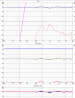
Simple test data generated with diffraction tool. Planar radiator 20x80 mm in some box. Mirror missing unchecked, Half space checked.
1. Hor -90...+90 deg, ver -90...+90 deg, step 5 deg
2. Hor -45...+45 deg, ver -90...+90 deg, step 5 deg
DI of the last one is lower because no data within +/-46...90 deg in hor plane, but otherwise looks quite believable.
1. Hor -90...+90 deg, ver -90...+90 deg, step 5 deg
An externally hosted image should be here but it was not working when we last tested it.
2. Hor -45...+45 deg, ver -90...+90 deg, step 5 deg
An externally hosted image should be here but it was not working when we last tested it.
DI of the last one is lower because no data within +/-46...90 deg in hor plane, but otherwise looks quite believable.
Rev. 2.0.30.0 (2019-11-05)
Main
* Added Redo command (Ctrl+Y) to context menu of crossover schematic.
Main
* Added Redo command (Ctrl+Y) to context menu of crossover schematic.
I've requested a feature for Merger and Kimmo was willing to implement that - thank you Kimmo
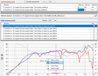
Request was for Merger to also allow an overlay curve. Below is an example where I'm merging a nearfield and far field data + the baffle simulation curve. Having a possibility to also show a 'long gated' and more smoothed response below those gives a bit of extra confidence that the baffle step slope will be correct. Hope other will find this useful too.
Request was for Merger to also allow an overlay curve. Below is an example where I'm merging a nearfield and far field data + the baffle simulation curve. Having a possibility to also show a 'long gated' and more smoothed response below those gives a bit of extra confidence that the baffle step slope will be correct. Hope other will find this useful too.
Attachments
Is there supposed to be any cabinet and baffles simulation for these 2 demo?
Epe-3W does not have diffraction project file (.vxb). It was not my speaker and I did not write cabinet dimensions and driver locations down. I can ask and create vxb if needed.
Kontiainen has now vxb file for W15LY inside the zip.
Some old revisions of those projects were using cabinet impact responses created with LspCAD 5.25.
Both zip files are fully updated anyway. All frequency responses are exported with Convert IR to FR, Merger project files .vxm created, responses merged and selected for drivers in project, and delays set to 0 us. Few component values are also changed but that's irrelevant.
Last edited:
Epe-3W does not have diffraction project file (.vxb). It was not my speaker and I did not write cabinet dimensions and driver locations down. I can ask and create vxb if needed.
Kontiainen has now vxb file for W15LY inside the zip.
Some old revisions of those projects were using cabinet impact responses created with LspCAD 5.25.
Both zip files are fully updated anyway. All frequency responses are exported with Convert IR to FR, Merger project files .vxm created, responses merged and selected for drivers in project, and delays set to 0 us. Few component values are also changed but that's irrelevant.
Wow! I am really impressed, I was just expecting something like: No, do not spend your time looking for the cabinet or baffle simulation, these informations were not available from the project owner.
Thank you very much! this is massive work and I am sure to make progress measuring and modding my own speaker build from a few years back.
- Home
- Design & Build
- Software Tools
- VituixCAD