Member
Joined 2003
You are right to measure on each drivers axis. Left and right angles is not necessary if the drivers are centred on the baffle, since the arrangement is symmetrical. However, if you want to take advantage of power & DI chart you need to measure full 180 degrees, 360 for the offset tweeter.The Vituixcad tutorial says to "Measure far field responses of woofer and mid-range driver and tweeter at 1000 mm in horizontal plane around the speaker."
So this is how I have done this;
1. Measured at 1 meter on tweeter axis (0-+/-60 degrees horizontal in 15 degree increments)
2. Measured at 1 meter on upper woofer axis (0-+/-60 degrees horizontal in 15 degree increments)
3. Measured at 1 meter on lower woofer axis (0-+/-60 degrees horizontal in 15 degree increments)
Remeasure distance and try to keep as close as possible, generally 1-2mm is not detrimental, to see the difference this has simply adjust the Z axis of your drivers by 1-2mm in the crossover and see.One pssible issue with my method is that mic distance to the baffle will vary slightly when adjusting mic height for the different drivers.
Generally design axis is tweeter axis, so the tweeter is enter red in the crossover at 0,0,0, and the x,y location of other drivers are entered relative to the tweeter.I see some also using the term 'design axis', I presume this means listening height..

Thank you very much for your input DcibeL!You are right to measure on each drivers axis. Left and right angles is not necessary if the drivers are centred on the baffle, since the arrangement is symmetrical. However, if you want to take advantage of power & DI chart you need to measure full 180 degrees, 360 for the offset tweeter.
You are right of course, I only measured the upper/lower woofers 0-60 degrees one way. The tweeter was measured both +/- since it is offset.
I hope I can still use my polar measurements in Vituixcad even though they are not full 180 degrees? I don't have a turntable, so this was a very tedious job, that i s why I took a shortcut with my limited measurements (0-15-30-45-60 horizontal).
Very good info, thanks!Remeasure distance and try to keep as close as possible, generally 1-2mm is not detrimental, to see the difference this has simply adjust the Z axis of your drivers by 1-2mm in the crossover and see.
Generally design axis is tweeter axis, so the tweeter is enter red in the crossover at 0,0,0, and the x,y location of other drivers are entered relative to the tweeter.
Like you say, normally listening axis is tweeter axis. But in this case tweeter height is 80cm from the floor and listening height is 95cm, so more on axis with upper midwoofer. But it works well, I guess it has something to do with the dispersion of the MTM configuration?
Last edited:
Member
Joined 2003
Yes, it can be a tedious process without turntable. I don't use one either, luckily ARTA or REW provide some automation still with file naming etc, so it doesn't take that long to do. I tape a polar map to the floor as a guide and rotate manually, the 30-60min it may take provides valuable information for design of a speaker that I intend to enjoy for years to come.Thank you very much for your input DcibeL!
You are right of course, I only measured the upper/lower woofers 0-60 degrees one way. The tweeter was measured both +/- since it is offset.
I hope I can still use my polar measurements in Vituixcad even though they are not full 180 degrees? I don't have a turntable, so this was a very tedious job, that i s why I took a shortcut with my limited measurements (0-15-30-45-60 horizontal).
With only 60 degree off-axis information, you will have polar map available with that limited information, and listening window may be useful too, but not enough information for in-room response, power response, DI.
Difference of 15cm at 2-3 meters listening distance is fairly minimal, only a couple degrees off-axis. By all means adjust the y axis of all drivers by 15cm in the crossover and see for yourself. I would tend to keep tweeter axis as design axis regardless, expecting that the speaker is not a permanent installation, you may decide to change listening height at any moment in the future. As well, most people don't listen with "head in a vice", so listening window, in-room response I find are more useful than single axis response at any angle.Very good info, thanks!
Like you say, normally listening axis is tweeter axis. But in this case tweeter height is 80cm from the floor and listening height is 95cm, so more on axis with upper midwoofer. But it works well, I guess it has something to do with the dispersion of the MTM configuration?
I absolutely agree with you about doing all measurements correctly.
This is my first venture into crossover design, and I realise there is alot of info to absorb. So I try to take a more simplistic route this time, just to be able to make a workable crossover that I can tweak over time. I have ordered a rotable TV stand for my next round of measurements.
There was something else I was a bit puzzled about, relating to nearfield measurements. This would all have been easier if I based the design on a regular two driver two way speaker, I find the MTM config confuses me abit.
So Vituixcad tutorial says this;
"Measure near field response of one woofer cone at 5 mm from center of dust cap. If two woofers have shared box, feed signal to both woofers and isolate (not brake) the other (which is not under test) gently with pillow to prevent midrange frequencies going to mic too much."
So I measure only one of the woofers nearfield, with the pillow muting midfrequencies from the other? Why not measure both nearfield with the other disconnected, since this is how Viyuixcad will interpret the speaker?
Your midbass drivers are sharing the box volume (I presume, as that is how LV Auditorium are).
With one disconnected, the other will work singularly in the whole volume and its bass response will be altered, and the disconnected driver will act as a PR (well, almost, because of the voice coil...).
No need to close measure both, a single near field measurement can be used for further merging with each of the drivers' separate far field measurements, as you did.
You can measure as you say IF each driver has its own volume.
Member
Joined 2003
With one speaker disconnected, the disconnected driver becomes a "passive radiator", so in-cabinet response will not be as you expect. The in-cabinet response will only be correct with both drivers connected as they're intended to be. So you want nearfield measurement of one driver without much "contamination" from the sound of the other nearby driver. For simple approach, take a sheet of plywood and lean it against the speaker as a shield. Pillow may work well enough too.
Is this the proper way to do things? It looks valuable but then...You are right to measure on each drivers axis. Left and right angles is not necessary if the drivers are centred on the baffle, since the arrangement is symmetrical. However, if you want to take advantage of power & DI chart you need to measure full 180 degrees, 360 for the offset tweeter.
Remeasure distance and try to keep as close as possible, generally 1-2mm is not detrimental, to see the difference this has simply adjust the Z axis of your drivers by 1-2mm in the crossover and see.
Generally design axis is tweeter axis, so the tweeter is enter red in the crossover at 0,0,0, and the x,y location of other drivers are entered relative to the tweeter.
Can you not measure all drivers on listening axis iso centre driver axis?
You don't need to move the mic then. ( only turn the speaker for horizontal off axis)
X and y are '0' for all drivers in the crossover screen.
To know z offset you take the individual 0degree on listening axis measurement and make a measurement with all driver connected on listening axis.
Then make them overlay each other till the match up.
Does did methode make sense?
Member
Joined 2003
Not good practice. It provides inaccuracy for simulation at listening distance of 2m+ if you are measuring at 1m for example, as well you become "locked in" to the driver orientation and simulation distance. Just measure at each driver's axis.Is this the proper way to do things? It looks valuable but then...
Can you not measure all drivers on listening axis iso centre driver axis?
You don't need to move the mic then. ( only turn the speaker for horizontal off axis)
X and y are '0' for all drivers in the crossover screen.
I hope you aren't using a USB mic / single channel measurement following this process. Not good enough for multi-axis data. Follow dual channel measurement process as outlined in the instructions for REW or ARTA, acoustic delay is inherent to the measurement when completed properly, all z axis = 0 if the baffle is flat.To know z offset you take the individual 0degree on listening axis measurement and make a measurement with all driver connected on listening axis. Then make them overlay each other till the match up.
Instruction for REW:
https://kimmosaunisto.net/Software/VituixCAD/VituixCAD_Measurement_REW.pdf
Instruction for ARTA:
https://kimmosaunisto.net/Software/VituixCAD/VituixCAD_Measurement_ARTA.pdf
Thanks Draki, yes the woofers share the volume.Your midbass drivers are sharing the box volume (I presume, as that is how LV Auditorium are).
With one disconnected, the other will work singularly in the whole volume and its bass response will be altered, and the disconnected driver will act as a PR (well, almost, because of the voice coil...).
No need to close measure both, a single near field measurement can be used for further merging with each of the drivers' separate far field measurements, as you did.
You can measure as you say IF each driver has its own volume.
This is very clarifying and exactly what I was looking for, thank you!
On to the next and final question wrt measurements;
"Measure impedance response with phase of one woofer if all drivers have own box. If drivers share the same box volume, they should be measured together in series or parallel - like in the final connection."
I have a DATS V3 so the actual measuring is easy. Since the woofers share a common volume they must be measured together like the tutorial says.
What I don't understand is how this combined measurement file can represent each woofers zma response, as it will be imported twice into Vituixcad?
You will set the "scaling" for the impedance to "0.5" from the default "1.00" (for each driver, so they will sum back to unity in the crossover simulation).On to the next and final question wrt measurements;
"Measure impedance response with phase of one woofer if all drivers have own box. If drivers share the same box volume, they should be measured together in series or parallel - like in the final connection."
I have a DATS V3 so the actual measuring is easy. Since the woofers share a common volume they must be measured together like the tutorial says.
What I don't understand is how this combined measurement file can represent each woofers zma response, as it will be imported twice into Vituixcad?
One mid driver of MTM is imported just once if driver is measured in horizontal plane only. Two driver instances are added to crossover, and they use the same response data. Different Y coordinate (+/-) create vertical directivity and lobing.as it will be imported twice into Vituixcad?
This enables also line arrays with tens of drivers, but just one response data.
Hi kimmosto,One mid driver of MTM is imported just once if driver is measured in horizontal plane only. Two driver instances are added to crossover, and they use the same response data. Different Y coordinate (+/-) create vertical directivity and lobing.
This enables also line arrays with tens of drivers, but just one response data.
I made separate horizontal measurements of upper and lower midwoofer since the baffle step response is different (less baffle around upper M).
When you say that I should use only one M, I find that a bit confusing. Can you please elaborate on this?
Member
Joined 2003
I don't understand why I would use only one measurement, when the two midwoofers are not horizontally axisymmetric?Since you’ve already measured both midwoofers individually, compare for yourself the difference in using 2 separate midwoofers each with their own unique response vs using 2 instances of the same driver, not including the second measurement set.
Why does kimmosto suggest this approach, when his tutorial is so meticulous about everything else?
The measurements differ 2-3dB at most, I don't know if this would be considered too much to only using one of them.
Being new in this game, I appreciate a consistent and easy to understand workflow🙂
Use both measurements , each for corresponing driver. Make sure the x,y,z values for each driver are correct, as well as listening distance, and placement in room if you want an indication of the boundary reflections as well.I don't understand why I would use only one measurement, when the two midwoofers are not horizontally axisymmetric?
Why does kimmosto suggest this approach, when his tutorial is so meticulous about everything else?
The measurements differ 2-3dB at most, I don't know if this would be considered too much to only using one of them.
Being new in this game, I appreciate a consistent and easy to understand workflow🙂
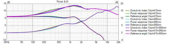
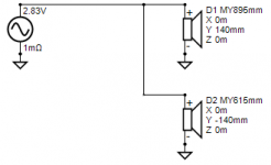
Quick simulation of MTM. Baffle 210x1000 mm, upper mid Y=895mm, lower mid Y=615mm, Dd=130mm, mic at 5 m while diffraction simulation. Both planes and positive and negative angles were exported from Diffraction tool.

Three XO variants were simulated and fundamental Power&DI traces saved to overlays:
1) Both drivers use data of lower mid Y=615 mm
2) Both drivers use data of upper mid Y=895 mm
3) Drivers use their own data Y=615+895 mm

Result stays close to same also without data in vertical plane and negative angles. Deviation from full data is probably less than 1 dB with this kind of typical MTM also in real life. That is "promised" in measurement instructions for simulation of circular drivers/horns without data in vertical plane. Smaller deviation is expected with shorter cabinets which reduce effect of vertical (Y) location.
Every user have to make own decision how much measurement data is captured for XO simulation. For example I don't usually measure vertical plane, negative angles and more than one driver per model. Assumption is that box design is healthy; symmetrical over vertical center line and long rounding and/or bevels. This cheating saves huge amount of time for example with line array projects.
Three XO variants were simulated and fundamental Power&DI traces saved to overlays:
1) Both drivers use data of lower mid Y=615 mm
2) Both drivers use data of upper mid Y=895 mm
3) Drivers use their own data Y=615+895 mm
Result stays close to same also without data in vertical plane and negative angles. Deviation from full data is probably less than 1 dB with this kind of typical MTM also in real life. That is "promised" in measurement instructions for simulation of circular drivers/horns without data in vertical plane. Smaller deviation is expected with shorter cabinets which reduce effect of vertical (Y) location.
Every user have to make own decision how much measurement data is captured for XO simulation. For example I don't usually measure vertical plane, negative angles and more than one driver per model. Assumption is that box design is healthy; symmetrical over vertical center line and long rounding and/or bevels. This cheating saves huge amount of time for example with line array projects.
Attachments
- Home
- Design & Build
- Software Tools
- VituixCAD