I have googled for quite a while, found some old instructions in this same thread that no longer work. But no, I genuinely never thought there even is a user manual, thank you!
But I can say is this: whatever the way to import speaker XML is, it's intuitive as hell! For I couldn't find it through interacting with the UI, and I have tried hard.
But I can say is this: whatever the way to import speaker XML is, it's intuitive as hell! For I couldn't find it through interacting with the UI, and I have tried hard.
Feature is much more complex than simple import which adds new records so it is called "Update database". It's located in context menu of driver table. Certainly difficult to find if right click does not work in the mouse.
Another option for adding single driver is using Paste button in Add new drivers window. That supports copy-paste from CLIO, LIMP, REW, loudspeakerdatabase, parts-express.com, speakerbench.com and VituixCAD driver xml. This is listed also in tooltip of Paste button.
So it's as intuitive and versatile as hell! The most common problem is oveverestimation of own intuition and assumption that freeware cannot have instructions.
I have read about "loudspeaker database" and about pasting. I couldn't find this database, though. I would never have guessed that the speaker database is actually accessed through the "Enclosure" tool - this is the step I was missing. Thank you. In my mind, drivers and enclosures are absolutely different concepts, even though used together, so I didn't even think of clicking it to see what's there.
I was looking at the "Drivers" tab, where I could seemingly do nothing. I can add drivers but not specify their parameters; right-clicking doesn't work anywhere (other than the graphs), and drag-and-drop works for XML files, but ends up with an error because it's not the kind of XML that's expected here.
One small request: did you think about enabling high DPI support? It should be very simple in a C# app. Right now the UI is perfectly usable, but the blurry text is painfully obvious.
Last edited:
...enabling high DPI support?
High DPI support in Windows Forms
So display scaling will be the only option with 2560x...4K...8K displays as long as VCAD should support also Win XP and Win 7.
Display scaling works in Win 10 quite okay though text edges are not very sharp with all scales. Older windows can't do even that.
Hm, it should be possible to enable high DPI entirely at runtime, without modifying the manifest or other static resources. Then you could check for the OS version at runtime, load the necessary WinAPI functions dynamically and call them only for Windows 10 (or 7 and 10). I know my C++ applications have no problem supporting per-monitor DPI on Windows 10 while still running fine on Windows 7 and Vista (I have dropped support for Windows XP ages ago so I don't know anything about that OS anymore).
So yes, I was wrong, while doable - it's not at all as simple as assumed it should be. Pity. It's not a major issue by any means, but the blurry text is somewhat harsh on the eyes.
Thank you for the awesome software!
So yes, I was wrong, while doable - it's not at all as simple as assumed it should be. Pity. It's not a major issue by any means, but the blurry text is somewhat harsh on the eyes.
Thank you for the awesome software!

I would never have guessed that the speaker database is actually accessed through the "Enclosure" tool.
With that logic Boxsim, BassBox, Unibox, Torres Box Tuning Calculator etc are suitable for designing empty or damped box without drivers. WinISD for something else.
Main program is crossover simulator using response data for driver components in the crossover so Driver as a tab name has at least one proper word.
Anyway, reading user manual and measurement instructions should reveal recommended design method, tools and order.
Thank you for this amazing software. I've tried looking through the manual and searching this thread extensively, so I'm extremely sorry if I've overlooked the answer. I'm wondering if there's any way to incorporate a particular driver's actual FRD into the enclosure tool. Similar to how you can add and view the effects of a diffraction response file.
When I'm tweaking my enclosure settings, it would be great to have the driver's frequency response factored in to the plot. That way I can see if peaks and valleys I'm creating are helping or hurting the driver's inconsistencies.
I believe BoxSim does this. You can load an FRD into the driver window, and that response curve gets applied to the simulation.
Last edited:
Member
Joined 2003
You can load whatever response you like to the enclosure tool "diffraction response" section, under the "align" tab.
Your approach may be a bit backwards through. In-room response at low frequency will be dominated by the room interaction, so to interrogate the response without room interaction, the low frequency response of the driver is equal to the near field response plus diffraction. With that in mind, the correct approach would be to simply load the cabinet diffraction into the "diffraction response" section of the enclosure design to view the full space response of the driver at low frequency.
Alternatively, the enclosure response, diffraction response, and far field measurement can all be combined using the merger tool.
Last edited:
Thank you for your help. It does seem I had this backwards. It also looks like the "half space response" field in the diffraction tool is exactly what I was asking for. The factory measurements go there, I check full space, I load that exported diffraction response into the enclosure tool. Does that sound like the correct workflow?
Member
Joined 2003
For what I think you want to achieve, yes that will work. The assumption would be that the manufacturer data is half space and accurate at low frequency, which they often aren't.
What I would do is just export the half space diffraction response, do not load the manufacturer data to the diffraction tool. Export the diffraction response.
Simulate the enclosure and export the SPL result.
Use the merger tool, load the enclosure SPL file as the "near field" response. Check the box for diffraction and load the diffraction response. Load the manufacturer data as the "far field" response. Adjust SPL and merge point for good overlap and save the result.
Member
Joined 2003
Hi Kimmo,
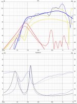
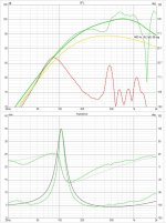
While trying to match bas reflex simulations to measurements I encounter a problem;
I cannot match the sims with the measurements because the ports are on the rear of a large cabinet.
I have performed farfield @4 meter (outdoor) and nearfield measurements of the cabinet.
When I add the nearfield measurements together I get a good match with the farfield measurement if I account for the time-of-flight delay in REW.
I can get a perfect impedance and cone respone / port response match in Vituixcad in the enclusure tool, but not a good matched total SPL response. The simulated total response is the same as when I add the port and cone measurement in REW without accounting for the time-of-flight.
Do have have a solution or workaround for this?
Thanks,
Kees
Hi Kimmo,
While trying to match bas reflex simulations to measurements I encounter a problem;
I cannot match the sims with the measurements because the ports are on the rear of a large cabinet.
I have performed farfield @4 meter (outdoor) and nearfield measurements of the cabinet.
When I add the nearfield measurements together I get a good match with the farfield measurement if I account for the time-of-flight delay in REW.
I can get a perfect impedance and cone respone / port response match in Vituixcad in the enclusure tool, but not a good matched total SPL response. The simulated total response is the same as when I add the port and cone measurement in REW without accounting for the time-of-flight.
Do have have a solution or workaround for this?
Thanks,
Kees
In calculator tool, function A+B (port +bass nearfield) do you fill number for time delay for port? If you play with delay number for port, you can see how different total spl could be.
Thanks for your reply, I know about that functionality (I did it in REW but is the same).
The nearfield, corrected, measurements line up perfectly with the freefield distance measurements, but I cant get the sims to line up.
I would be nice to also have the option in the enclosure tool (or a workaround)
the reason I want the sim to line up with the measurements is that I would like to be able to get insight in maximum excursion and port velocity and power
Last edited:
At the moment Merger tool does not have delay parameter for individual LF responses. That would work okay to listening window, but effect is opposite to rear sector so it's not the best approach for merged off-axis responses. The same problem exists if summing is done with Calculator and simple delay. Z mm parameter with 3D geometry calculation is needed to improve whole 360 deg sector.
Unchecking BS checkbox of individual LF response in Merger excludes baffle effect response so that's another cheap thick to reduce excessive level at high bass if port is not in front panel.
The best workaround VituixCAD supports at the moment is using main program to sum acoustic signals of separate cones and ports located around the box because it's the only tool able to sum responses in 3D space using geometry calculation and response interpolation.
1) Create separate response sets to full space (in hor and ver planes) for cone(s) and port(s). This is done with Diffraction tool: near field measurement of the cone/port is loaded to Half space response text box, and off-axis responses are exported with Directivity option. Each radiator must have own on-axis i.e. mic is located in the center point of each cone/port.
2) Driver is created to main program for each cone/port radiator. Response sets are loaded to drivers. Vent responses should be scaled with radiating area compared to cone.
3) Separate radiators are added to crossover as driver instances in parallel. Driver instances are located with X,Y,Z,R,T parameters how they are in real cabinet. Cone is at the origin XYZ=0,0,0 mm, and vent(s) for example XYZ=0,-300,400 mm, RT=180,0 deg.
4) Total response is exported. This is new total LF response to far field which is merged (with Far field option) with actual far field measurements or responses already merger with standard procedure. Blending frequency should be quite low and range wide e.g. 2 octs. to merge phase and directivity smoothly.
BUT all this is not really mandatory. Power response plot is okay no matter delay and location of the port. So designing flat power within and below predicted transition range works fine no matter small error within listening window. On-axis may show minor bump where cone and port signals are crossing. Ignoring that and looking power will give proper result.
P.S. Using power response as a main parameter helps also with gradient radiators.
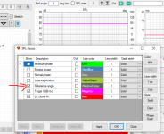
A very simple question, probably already asked before, but: is it possible to deselect the summed response function, while using two or more drivers in the x/o schematic?
I would like to make overlays of various individual active response shaping circuits in order to compare those. Having to deala with summed responses mucks up the whole idea.
I would like to make overlays of various individual active response shaping circuits in order to compare those. Having to deala with summed responses mucks up the whole idea.
Member
Joined 2003
- Home
- Design & Build
- Software Tools
- VituixCAD