Hi Kimmo,
many thanks for adding the xilica solaro48k in the current update!
However, I noticed that you still need to insert Q=1.41 in vituixcad where in Xilica designer you input 1, is this a delibirate choice?
This is, in my opnion, not the most convenient, since now you cant just copy paste setting to solaro.
Thanks,
Kees
However, I noticed that you still need to insert Q=1.41 in vituixcad where in Xilica designer you input 1, is this a delibirate choice?
Yes, because it's the equation Xilica uses e.g. in XConsole 9 for XA and XP series. XConsole shows calculated Q while adjusting BW which makes things much easier compared to Designer 4.3 for Solaro.
I try to tell this also in user manual.
* Xilica Solaro 48k.
Note! Peak/Notch and Shelving LP/HP filters: Q=1.41/BW, BW=1.41/Q.
* Xilica XA/XP 96k.
Note! Peak/Notch and Shelving LP/HP filters: Q=1.41/BW, BW=1.41/Q.
The best option would be showing BW parameter in the grid and calculating Q internally. I will consider that.
P.S. I also added Marani P series to DSP list, but I found out that peak/not filter is constant Q. Program does not have biquad coefficient calculation for that type so feature was not yet published.
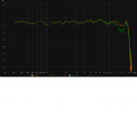
here's a comparison of the earthworks m30 and emc8000 that I bought in 2012. both with no cal.Thank you for your input!
I created a new thread here to sumarize the information i got in this thread, and to avoid polluting this one.
I decided that i'll go with the ECM8000 and will use the CSL Umik-1 to calibrate it for now.
there is some difference in the very low end Aswell .
Attachments
As one of those people who is stuck with "limited space" for measurements the most difficult part of the measurement process for me is always the lower midrange area where you are trying to splice a windowed far field high frequency measurement to a low frequency nearfield measurement that has simulated baffle step response applied.Also recommended design procedure includes measurements closer than final listening distance, simulation of baffle loss at LF and scaling from near to far field with area and distance only. So dual channel is not the only requirement, and there's no accurate solution available as long as measurements are done in limited space with some reflections.
If your microphone and sound card are decent and reasonably calibrated this is the region where you are likely to have the most measurement error, often without even knowing you have a significant error.
Insufficient resolution of the high frequency measurement just above the splicing point can give a misleadingly smooth response, and errors in the extrapolated low frequency slope of the windowed measurement (due to DC offset, lack of resolution etc) can result in misleading splice points where you end up with a significant gain error between the two measurements while trying to make the curves exactly join.
Having a response that looks artificially smooth in the lower midrange area is not neccessarily a big problem for the final response but a gain error during splicing is.
For anyone who is new to taking measurements these kind of issues can be a bit of a challenge - even just understanding what the pitfalls are in this type of spliced measurement is half the battle.
I think you're talking about the point around the time window.
Because that point can have a bit of error depending on the type of time window that's being used.
This error is roughly gone around 2x time window frequency.
So sometimes it's advisable to use different types on time windows to get a better idea of what is going on.
Luckily the baffle step can be modeled pretty well.
So one can estimate a proper stitch point.
Although it does depend on how crazy the baffle design is.
Also things like cardiod speakers are a bit of a strange animal.
For big things like line arrays this method won't really work anymore.
But yes that part can be a bit finicky.
Just make sure the walls are anti-parallel to the measuring setup and there is enough space behind the speaker as well.
And of course the biggest distance between ground en ceiling (seen from the woofer, not the middle of the cabinet)
Sometimes a combination with a groundplane measurement will also help.
Lately I have used Cosine window function more and more for mid-woofers and woofers. That does not overshoot above typical splicing point as much as Tukey 0.25-0.50 or undershoot as much as Hanning. Ending point to the last dip in ETC before the first (floor) reflection.
Yeah Cosine seems to work pretty nice here as well ")
I also get pretty decent results with Hann 25% , but unfortunately this is not (yet?) available in VituixCAD
When overlapping time windows are being used, one can squeeze in a few more Hz.
Sometimes one can also allow more dips (reflections/interference) to at least get a good sense of were the bafflestep starts.
After that is determined, one could use a better window for calculating the filters.
Totally equal. Looks that Tukey is more official/common name for flat top Hanning while Hann 12% and 25% are known in ARTA. See Window function
When overlapping time windows are being used, one can squeeze in a few more Hz.
Can you please explain with an example?
Ah, good to know.Yes that is correct. Known (and described) as semi-dual.
In fact, I don't know how people use USB mics for their measurement accurately, because if your input channel into your laptop is a totally different device (or USB stream) from your output channel, then the timing correlation between output and input is lost. I still find many speaker builders using USB mics like the MiniDSP one.
Member
Joined 2003
Delay is determined acoustically, taking 3 measurements, one of each speaker then both together in parallel. Delay of one driver is adjusted until the summed response matches the measurement of both drivers playing together. VituixCAD includes a tool for this. It is accurate, but the limitation is single axis response only, similar to what you get from Xsim. Same argument could be made for "why do people still use Xsim".
USB mics are a good plug and play option for things like room acoustics, measurement of complete speaker system, but not the best tool for design. This topic has been beaten to death here.
USB mics are a good plug and play option for things like room acoustics, measurement of complete speaker system, but not the best tool for design. This topic has been beaten to death here.
USB audio interfaces introduce a variable delay due to the software layer in the laptop. The gap between the precise microsecond at which your application pumps out the USB data to the Windows OS and the microsecond at which the audio interface receives it varies from iteration to iteration. I used to see variations of a few msec 10+ years ago when I was using Speaker Workshop and Windows XP.Delay is determined acoustically, taking 3 measurements, one of each speaker then both together in parallel. Delay of one driver is adjusted until the summed response matches the measurement of both drivers playing together. VituixCAD includes a tool for this. It is accurate, but the limitation is single axis response only, similar to what you get from Xsim. Same argument could be made for "why do people still use Xsim".
USB mics are a good plug and play option for things like room acoustics, measurement of complete speaker system, but not the best tool for design. This topic has been beaten to death here.
Therefore, if the output device is one USB audio interface and the input mic is connected to another, the application (say, SW or ARTA) cannot make consistent calculations of the time lag. This messes up the relative phase between drivers.
This has been beaten to death too on DIYaudio, maybe you didn't notice because you never faced this problem.
Now with the dual-channel technique ARTA offers, this problem is taken care of, but only if the output and input signals are being clocked through one single USB device.
Member
Joined 2003
I understand the timing problem, you've completely misunderstood the content of my post. The measurement method that I explain, and what people do with USB mics negates the timing errors but leaves you with a delay value that is only valid for that single measurement set. It is a completely acoustic comparison of one measurement to another, timing errors do not factor in. Perhaps the manual section on the time align function could provide further clarity:
VituixCAD help 2.0
No need to try and educate me on dual channel operation, I "converted" years ago, but still keep my Dayton Omnimic for the reasons I state above.
VituixCAD help 2.0
No need to try and educate me on dual channel operation, I "converted" years ago, but still keep my Dayton Omnimic for the reasons I state above.
The method mentioned in your post and in the help page of VituixCAD is one method of arriving at difference between acoustic centre distances. I have never felt the need to use it because I've always measured both drivers keeping the mic at one position, thus allowing the measured data to capture the difference between the acoustic centre distances in the form of a phase difference. So, as far as VituixCAD is concerned, I make it think that I have two point source drivers with coincidental acoustic centres and a small phase difference in some frequency range.I understand the timing problem, you've completely misunderstood the content of my post. The measurement method that I explain, and what people do with USB mics negates the timing errors but leaves you with a delay value that is only valid for that single measurement set. It is a completely acoustic comparison of one measurement to another, timing errors do not factor in. Perhaps the manual section on the time align function could provide further clarity:
VituixCAD help 2.0
No need to try and educate me on dual channel operation, I "converted" years ago, but still keep my Dayton Omnimic for the reasons I state above.
This has nothing to do with the problem I faced due to random delay in USB interface readings.
Member
Joined 2003
This has nothing to do with the problem I faced due to random delay in USB interface readings.
It has everything to do with determining delay between drivers with a USB mic and how people use them, which was your question. Timing error is easily "corrected" by using min phase calculation or by using some part of the measured data such as the impulse peak as a timing reference. Time of flight information is not available for the reasons you describe, so attempt to lock the FFT window start time is pointless with a single channel measurement. In any case, USB mic is not proposed for design work here so we can move on.
For dual channel measurement with complete off-axis information, just follow the guide for VituixCAD. Mic should be placed on axis with each driver and constant distance to baffle. Measuring all drivers at single mic location is not ideal as it will require that you complete full horizontal and vertical measurement for accuracy of power response, as well the x,y location will not be adjustable in simulation since 0deg measurement is not on-axis with the driver. If mic location remains stationary, x,y,z location of drivers should remain at 0,0,0.
- Home
- Design & Build
- Software Tools
- VituixCAD