Member
Joined 2003
Hi mlee,
Kimmo may hate me for this, but I've attached a document that may help you.
I have tried to make it clear in the document, that designing without measurements is only intended to provide an understanding of the tools and process, anything you intended to design with accurate result should be completed by 2-channel measurement process for real-world data.
Attachments
Hi mlee,
Kimmo may hate me for this, but I've attached a document that may help you.
I have tried to make it clear in the document, that designing without measurements is only intended to provide an understanding of the tools and process, anything you intended to design with accurate result should be completed by 2-channel measurement process for real-world data.
Perfect, thanks for the information! Understood it is for simulation only and does not replace 2-channel actual measurements.
Understanding VituixCAD geometrical design conventions
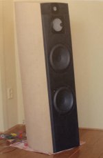
I am studying the VituixCAD system in preparation of measuring and designing the crossover, and right now i am uncertain regarding the tilt of the baffle.
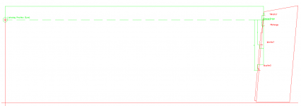
As can be seen on the attached images, the baffle tilts backwards by 5 degrees in my way of telling.
If i get the geometrical design convention of VirtuixCAD correctly, it means a tilt of -5 degrees. Am i correct in this?
Also just to check, if listening distance is 3000mm at a height of 990mm above floor, list-dist is Z=3000mm and where floor is mentioned the distance is Y=-990mm. Am i correct?
I am studying the VituixCAD system in preparation of measuring and designing the crossover, and right now i am uncertain regarding the tilt of the baffle.
As can be seen on the attached images, the baffle tilts backwards by 5 degrees in my way of telling.
If i get the geometrical design convention of VirtuixCAD correctly, it means a tilt of -5 degrees. Am i correct in this?
Also just to check, if listening distance is 3000mm at a height of 990mm above floor, list-dist is Z=3000mm and where floor is mentioned the distance is Y=-990mm. Am i correct?
Attachments
Member
Joined 2003
Hi mlee,
Kimmo may hate me for this, but I've attached a document that may help you.
I have tried to make it clear in the document, that designing without measurements is only intended to provide an understanding of the tools and process, anything you intended to design with accurate result should be completed by 2-channel measurement process for real-world data.
Why would somebody hate you for that?
Totally legit way of getting a (very) rough idea about a design.

Method has been used for many years by people, so don't see what is wrong with it?
Works fine before one has to actually buy/get the actual drivers or has to spend time measuring stuff.
Of course it's only an estimate, but I think that is rather obvious.
Thanks for the response, Just to be sure i understand what you mean with downwards:Tilt - positive value for upwards tilt, negative value for downwards tilt.
Looking at my speaker as shown in the picture, is that what you call a downwards tilt?
Member
Joined 2003
Why would somebody hate you for that?
Totally legit way of getting a (very) rough idea about a design.
Method has been used for many years by people, so don't see what is wrong with it?
Works fine before one has to actually buy/get the actual drivers or has to spend time measuring stuff.
Of course it's only an estimate, but I think that is rather obvious.
Same reason that single channel measurement is not the recommended process. Often there is not a complete understanding of the shortfalls, inaccuracy and missing information which can lead to a lot of misunderstandings of the simulation result vs real world result. People often follow this simulation method as a "shortcut" to design using only simulated data, when it needs to be made clear that if you want reliable results, then this simulated data needs to be deemed "not good enough", and the instruction should be employed only to familiarize with the tools and design process. It may be obvious to you and me, but for the inexperienced newcomer, probably not.
In fact, the entire reason I wrote the document was resulting from discussion with someone who was trying to follow an instruction from another site. The site was using some older software that included only single axis of information, and was misleading, indicating that the simulated response was good enough for accurate off-axis simulation, and completely glossed over the lack of known difference in acoustic centre when multiple drivers are employed. I wrote the document to use modern tools (VituixCAD) and to try to convey the shortfalls accurately.
It has been made clear over and over again in this thread, that the recommended process with VituixCAD is to design using 2-channel measured data, which is why Kimmo may hate me for providing an instruction to the contrary.
Last edited:
Member
Joined 2003
Thanks for the response, Just to be sure i understand what you mean with downwards:
Looking at my speaker as shown in the picture, is that what you call a downwards tilt?
I would say that your speaker tilts upwards.
I am studying the VituixCAD system in preparation of measuring and designing the crossover, and right now i am uncertain regarding the tilt of the baffle.
As can be seen on the attached images, the baffle tilts backwards by 5 degrees in my way of telling.
Check posts #309 and 310 in this thread: VituixCAD v2 - Page 9
As long as you make the shortfalls (very) clear, I still don't see why someone would have something against it?Same reason that single channel measurement is not the recommended process. Often there is not a complete understanding of the shortfalls, inaccuracy and missing information which can lead to a lot of misunderstandings of the simulation result vs real world result. People often follow this simulation method as a "shortcut" to design using only simulated data, when it needs to be made clear that if you want reliable results, then this simulated data needs to be deemed "not good enough", and the instruction should be employed only to familiarize with the tools and design process. It may be obvious to you and me, but for the inexperienced newcomer, probably not.
In fact, the entire reason I wrote the document was resulting from discussion with someone who was trying to follow an instruction from another site. The site was using some older software that included only single axis of information, and was misleading, indicating that the simulated response was good enough for accurate off-axis simulation, and completely glossed over the lack of known difference in acoustic centre when multiple drivers are employed. I wrote the document to use modern tools (VituixCAD) and to try to convey the shortfalls accurately.
It has been made clear over and over again in this thread, that the recommended process with VituixCAD is to design using 2-channel measured data, which is why Kimmo may hate me for providing an instruction to the contrary.
I also don't see what that would be the contrary.
If people still decide themselves to ignore all those things, that's their own fault and responsibility for having poor end-results.
Educating people is much better (and safer) than keeping them in ignorance by stating something must be done a certain way.
Kimmo may hate me for this
Also recommended design procedure includes measurements closer than final listening distance, simulation of baffle loss at LF and scaling from near to far field with area and distance only. So dual channel is not the only requirement, and there's no accurate solution available as long as measurements are done in limited space with some reflections.
We can just try to make good acoustic design and select good sounding high quality components and provide response data for XO design with as few inaccurate simulations as possible. This has been my goal so I won't provide easy & rapid tools and instructions and encourage to design crap intentionally.
In addition, better methods are not expensive and any...much slower so why should anybody use, make instructions or recommend for others?
Also recommended design procedure includes measurements closer than final listening distance, simulation of baffle loss at LF and scaling from near to far field with area and distance only. So dual channel is not the only requirement, and there's no accurate solution available as long as measurements are done in limited space with some reflections.
...
What is two channel measurement? Is it the same as what is described in the ARTA documentation, where one channel of the audio interface is used for loopback for accurate timing, and the other channel has the acoustic data from the mic?
Check posts #309 and 310 in this thread: VituixCAD v2 - Page 9
Thanks, clarified my question. So in my case it is +5 degrees.
(Also another post added to the clarification)
Next step a turntable that can handle size and weight (80kilo) . Will be using a thick round table top of ~90cm with a center bearing and rollers near the edge.
Interesting project to finalize the design that started in 2006( the picture is from that year).
What is two channel measurement? Is it the same as what is described in the ARTA documentation, where one channel of the audio interface is used for loopback for accurate timing, and the other channel has the acoustic data from the mic?
Yes that is correct. Known (and described) as semi-dual.
Thanks, clarified my question. So in my case it is +5 degrees.
(Also another post added to the clarification)
Next step a turntable that can handle size and weight (80kilo) . Will be using a thick round table top of ~90cm with a center bearing and rollers near the edge.
Interesting project to finalize the design that started in 2006( the picture is from that year).
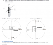
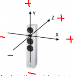
The cause of my confusion about the negative or positive angle comes from the picture as shown in the VituixCAD_Measurement_Arta.PDF. The angle convention in vertical plane , i would interprete that the angle of a baffle tilting back is a negative angle. But in the Diffraction tool, i simulated with different angles and a positive angle was needed.
Ahhh, just a phase i am going through ;-)
Attachments
")
Member
Joined 2003
We can just try to make good acoustic design and select good sounding high quality components and provide response data for XO design with as few inaccurate simulations as possible. This has been my goal so I won't provide easy & rapid tools and instructions and encourage to design crap intentionally.
In addition, better methods are not expensive and any...much slower so why should anybody use, make instructions or recommend for others?
In my case, I wrote the instruction for someone who wanted to get an understanding for the software tools and response processing while waiting for purchases of mic, USB interface, jig resistors etc in the mail. It is not to encourage design with crap data, but to provide introduction to concepts of full space, half space, diffraction, baffle step, cabinet model, as well as to clarify the limitations of such process that were not clear from another similar instruction. I tried to follow a process that is somewhat similar to the response processing that is done with real measurements, so that when the parts arrive and jig is built there is already some familiarity when following the measurement guide for VituixCAD.
What I usually recommend for measurement setup costs less than CAD$500, and as far as hobbies go that is a fairly small cost of entry, and can even be much cheaper. There is little excuse these days to design using only the manufacturer data sheet.
But in the Diffraction tool
Baffle is rotated in Diffraction tool and mic/ear stays in fixed position, but sign of angle is inverted in exported response files to be compatible with the main program and measurement instruction.
So read & follow measurement instructions and try to forget Diffraction tool.
- Home
- Design & Build
- Software Tools
- VituixCAD