Thanks for the clarification. Let me try your suggestions.
Values for Qa and Ql seem to be immaterial once a large volume (9999) litres is chosen.
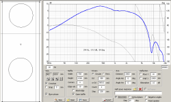
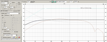
I've attached the diffraction and the enclosure screens. Do they look ok? I guess Qtc of 0.707 is ok?
The crossover dropdown lists each driver twice (one for front and rear of each dipole). Which crossover would one pick on the enclosure screen?
Still a lot of learn - what does half space export? should I include directivity? etc. will go through the manual.
Values for Qa and Ql seem to be immaterial once a large volume (9999) litres is chosen.
I've attached the diffraction and the enclosure screens. Do they look ok? I guess Qtc of 0.707 is ok?
The crossover dropdown lists each driver twice (one for front and rear of each dipole). Which crossover would one pick on the enclosure screen?
Still a lot of learn - what does half space export? should I include directivity? etc. will go through the manual.
Attachments
Member
Joined 2003
That's right, Qa and Ql are irrelevant when there is no box to load the driver. Are you going to stuff your entire room with insulation? ")
Qtc "alignment" parameters also irrelevant when you manually enter the enclosure size. Clicking on Qtc of 0.707 will adjust your closed box size accordingly which you won't want.
Half space response on the diffraction tab doesn't export anything, the button is for loading your driver 2pi response such as near field measurement to have diffraction applied to it.
Crossover function for enclosure selection is geared towards active filtering of subwoofers, to include the filter response in the result. There is not much to be gained here for your open baffle full range driver project.
I do want to use active xo/filter for Full Range to Woofers.
I never gave much thought to which driver parameters are required for different responses since in Basta you enter driver parameters, design the box/baffle and choose the response to view.
Is this correct?
- Enclosure considers T/S parameters but does not consider baffle dimension or driver's location on the baffle.
- Diffraction does not consider T/S but considers baffle size, driver size, count and position, mic position and floor reflection
Does the crossover design consider T/S?
If I choose the diffraction response in the Enclosure design does it (need?) factor the driver's parameters?
BTW, if I click "Auto align" I get an error "Alignment not succeeded alpha <= 0".
Is there a way to look at a driver/system response which factors the filter, t/s parameters and baffle design/driver position?
Maybe you read the manual first, but I think I know what you want to do.
1. Use enclosure tool, select your driver, enter closed box 9999l, export SPL and impedance (Z) using buttons in upper right corner, save responses
2. Use diffraction tool, enter baffle and driver size, load previously exportet SPL response to half space window, check full space, directivity, vertical plane and open baffle check boxes, Export responses
3. Use main tool. In drivers window open previously exported responses in frequency and impedance windows.
4. Repeat steps for every speaker type (sub, woofer, mid etc)
5. Add wire from generator to speaker(s) and start fiddling with cross over
Member
Joined 2003
Enclosure considers values present in that section of the program, nothing more.- Enclosure considers T/S parameters but does not consider baffle dimension or driver's location on the baffle.
Diffraction considers values entered in that section of the program, nothing more.- Diffraction does not consider T/S but considers baffle size, driver size, count and position, mic position and floor reflection
Crossover design considers frequency response and impedance data as you provide, nothing more. Real world measurements following CTA-2034-A process is the design intent of VituixCAD, follow the measurement design guide for ARTA and REW for more information.Does the crossover design consider T/S?
It just takes the enclosure response and combines with the diffraction response, suggest you try it out and see, should be obvious what is going on there.If I choose the diffraction response in the Enclosure design does it (need?) factor the driver's parameters?
Last edited:
@Kovapuhuja, thank you so much. I will give this a try.
Ok, so the ideal thing is to use real world measurements. I'm new to these designing tools. Are there any simulations (or parts of simulations e.g below or above a range) that I can use to get any idea about a driver + design just based on T/S parameters of the driver?
Ok, so the ideal thing is to use real world measurements. I'm new to these designing tools. Are there any simulations (or parts of simulations e.g below or above a range) that I can use to get any idea about a driver + design just based on T/S parameters of the driver?
One more thing about Parts Express. At the moment there is systematic error with moving mass. Name is "Moving Mass Of Diaphragm (Mmd)" without unit though values are Mms in grams.
Hello Kimmosto,
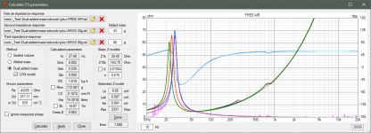
I measured JL 12W3V3-4 using REW, the result looks good in REW, but when I exported data from REW and import to VituixCAD to calculate the T/S parameters, there was big error like this.

In REW the result is good, BL is very flat, and John also thinks it looks good.

I'm using the lastest version of VituixCAD which was update today.
^Screenshots don't help. You must attach or send all three impedance response files to play with.
I can see from magenta curve that quality of measurements is not good enough and error in solving is not big surprise. Usually clicking 'LOG model' or 'Ignore measured phase' or swapping 'Added mass' and 'Dual added mass' helps solver to find some decent result.
I can see from magenta curve that quality of measurements is not good enough and error in solving is not big surprise. Usually clicking 'LOG model' or 'Ignore measured phase' or swapping 'Added mass' and 'Dual added mass' helps solver to find some decent result.
i wonder why the 'polar map' for 'directivity graph' is showing a 70db span when i choose a 50db span in the 'options' meny the spl graph is shown with the 50db span though
Polarmap can have useful visualisation also outside specified SPL range. Sharp crop of color could lose information especially when normalization is on. SPL span exists within red and magenta. Color gradient above maximum is from red to white, and below SPL minimum from magenta to black. Overflow and underflow transitions happen within major interval.
^Screenshots don't help. You must attach or send all three impedance response files to play with.
I can see from magenta curve that quality of measurements is not good enough and error in solving is not big surprise. Usually clicking 'LOG model' or 'Ignore measured phase' or swapping 'Added mass' and 'Dual added mass' helps solver to find some decent result.
Sorry,I forgot to upload the files. View attachment NO MASS.txt View attachment 2MASS.txt View attachment 4MASS.txt
I tried , but I could not solve the error.
But if I input the T/S parameters generated by REW, it can be used in VituixCAD.
I know I still can optimize the measurement by using new mass values.
Last edited:
That was tricky. Solving of extended impedance parameters required suitable initial values to get first acceptable result. After that everything goes smoothly.
Thank you Kimmosto. I input new value in Extended Z model area, the error is smaller.

Are these T/S parameters good to use?
Do you know why this happened? Can you make it more simple?
^Download and install the latest build manually. It should be able to calculate extended Z model parameters without entering initial values manually.
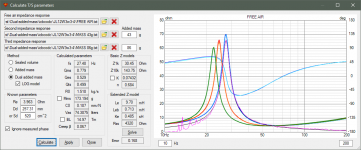
Set frequency maximum of chart to 200-400 Hz, and impedance maximum to 80 ohm that you could see peaks of all three Z response groups. That helps comparing simulated and measured responses, and shows when creep beta of LOG model is really okay.
The smallest error without phase response iteration is about 0.168. See attached image. Click Calculate to repeat solving if error is not okay.
Normally measuring of T/S parameters is not needed if manufacturer has published datasheet. Parameters of your driver are also available.
Purpose of whole Enclosure tool is not to make accurate science with dual added mass method and fancy creep modes. Just help product selection and calculate few simple enclosure parameters such as volume and ports or type, added mass and count of passive radiators.
Attachments
Last edited:


Member
Joined 2003
What are the benefits of the dual added mass?
Or do you have a link to some papers about it?
John (the author of REW) told me to use that, it's more accurate than th old single added mass method, and REW support that methodology.
Paper has been shared ,you can check it.
What are the benefits of the dual added mass?
* BL is a bit more accurate.
* No need to measure Re.
Difference to single added mass is usually insignificant so dual mass is not so important for diyers and box designing IMO. Knowing accurate BL and Mms would be more important for driver manufacturers assuming that individual test samples represent whole production. Unfortunately that is not common.
Knudsen LOG model and others including suspension creep is not the same as simulation with standard T/S parameters having constant Cms and Rms. Simulation with suspension creep needs simulator supporting creep parameters - R0, C0 and Creep Beta in this case. In practice it's not easy to use parameters calculated with 'LOG model' checked outside VituixCAD Enclosure.
- Home
- Design & Build
- Software Tools
- VituixCAD