Hi Kimmosoto, as usual, thank you for your work on this amazing tool.
From my point of view, you work is as important as other open softwares like REW, Rephase, etc etc, etc...
You are participating to spread the good words (CTA etc etc) on moderns speaker designs with folks like Amir, Erin etc etc etc
Can't thx you enough")
From my point of view, you work is as important as other open softwares like REW, Rephase, etc etc, etc...
You are participating to spread the good words (CTA etc etc) on moderns speaker designs with folks like Amir, Erin etc etc etc
Can't thx you enough
Limiting feature is easy to switch off while copy/export...
That is done in the latest build a minute ago.
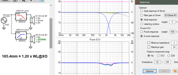
* Added optimizing of predicted in-room response
Predicted in-room includes early reflections (44%) in addition to listening window (12%) and sound power (44%). Partial ER could be useful if some bad features of ER are not clearly visible in power response.
For example simulation which might explain my sleeve constant c-c = 1.2 x wave length @XO. Rule of thumb would be c-c = 1.08 x wave length @XO when optimized by power response only. Radiators are omni-polar in both cases so sleeve constant is quit much simplified.
Attachments
Last edited:
You should also export measurement data from 5 Hz to 40 kHz with 48 ppo to respect internal scale of VituixCAD.
Page 8 in measurement instructions.
kimmosto
Excuse me, in the enclosure design module of Enclosure, why the filling option of sound-absorbing cotton is not added? What are the reasons and considerations? There is this option in Lsp CAD, but I am not sure how accurate it is.
Thank you again for making such an excellent and easy-to-use software, especially the baffle drop module, which is the most comprehensively evaluated and easy-to-use software I have used so far.
why the filling option of sound-absorbing cotton is not added? What are the reasons and considerations? There is this option in Lsp CAD, but I am not sure how accurate it is.
Simulation of filling is not important imo. Accurate simulation is very complex which makes programming difficult for different multi-volume boxes such as band bass.
LspCAD changes virtual volume and Qa by percent value. There is two very simple sleeve functions without much connection to reality. No selection for location, material and density/quantity i.e. how tight or loose it is finally installed. So it's as valuable/worthless as random playing with Qa and Vb.
2.0.67.0 (2021-04-24)
Merger
* Added 'Show near' checkbox to show/hide individual near field LF responses.
* Enabled Count=0 for LF responses.
Merger
* Added 'Show near' checkbox to show/hide individual near field LF responses.
* Enabled Count=0 for LF responses.
Fading out from diyaudio. I can continue at 'VituixCAD v2' on HTguide with some conditions.
Sad to see you leave. I've just got my first question today... Maybe someone else can answer that for me:
Is it valid to correct ground plane measurements by the difference of the diffraction simulations with normal baffle height and twice the baffle height? And if so, am I to apply that correction to the off-axis measurements as well?
https://i.ibb.co/ydgFD3y/diffraktion.png
Is it valid to correct ground plane measurements by the difference of the diffraction simulations with normal baffle height and twice the baffle height? And if so, am I to apply that correction to the off-axis measurements as well?
https://i.ibb.co/ydgFD3y/diffraktion.png
Member
Joined 2003
Sad to see you leave. I've just got my first question today... Maybe someone else can answer that for me:
Is it valid to correct ground plane measurements by the difference of the diffraction simulations with normal baffle height and twice the baffle height? And if so, am I to apply that correction to the off-axis measurements as well?
https://i.ibb.co/ydgFD3y/diffraktion.png
I'm not a ground plane expert but my understanding is that the whole point of a ground plane measurement is to obtain reflection free low frequency response. If you've measured correctly, then you should not be applying diffraction compensation, the diffraction is already included in the measurement.
For some comparison, compare your ground plane measurement to a near field measurement with baffle diffraction simulation applied.
If you're splicing the ground plane measurements with a normal far field measurement, you may find that only a single ground plane measurement is needed, spliced with the full off-axis far field measurements at normal height.
A ground plane measurement is a far field measurement where you move the speaker so close to the boundary that it has a predictable effect: a 6dB higher measurement until you get close to the first dip of the comb filter.
It has it's own problems like a changed diffraction response because of the mirror image, comb filtering if you can't put the measured driver close enough to the ground, and you have to have a perfectly reflective floor (epoxy screed garage - jackpot!), but it gives me a longer time window - twice as long as with the speaker on a stand at half room height - before reflections arrive for quasi anechoic measurements. Audio Precision has an application note about loudspeaker measurements with two pages about ground plane measurements. I found the pdf without having to log in: https://www.admess.de/tl_files/adme...n/AppNote - Loudspeaker EA Measurements-1.pdf
My guess is that I could correct for the different diffraction with the two simulated diffraction responses on-axis, but I'm just an amateur so I hope for a second opinion of someone who knows about this (And I have no idea if this can be applied off-axis, too.)
It has it's own problems like a changed diffraction response because of the mirror image, comb filtering if you can't put the measured driver close enough to the ground, and you have to have a perfectly reflective floor (epoxy screed garage - jackpot!), but it gives me a longer time window - twice as long as with the speaker on a stand at half room height - before reflections arrive for quasi anechoic measurements. Audio Precision has an application note about loudspeaker measurements with two pages about ground plane measurements. I found the pdf without having to log in: https://www.admess.de/tl_files/adme...n/AppNote - Loudspeaker EA Measurements-1.pdf
My guess is that I could correct for the different diffraction with the two simulated diffraction responses on-axis, but I'm just an amateur so I hope for a second opinion of someone who knows about this
(And I have no idea if this can be applied off-axis, too.)Member
Joined 2003
A ground plane measurement is a far field measurement where you move the speaker so close to the boundary that it has a predictable effect: a 6dB higher measurement until you get close to the first dip of the comb filter.
It has it's own problems like a changed diffraction response because of the mirror image, comb filtering if you can't put the measured driver close enough to the ground, and you have to have a perfectly reflective floor (epoxy screed garage - jackpot!), but it gives me a longer time window - twice as long as with the speaker on a stand at half room height - before reflections arrive for quasi anechoic measurements. Audio Precision has an application note about loudspeaker measurements with two pages about ground plane measurements. I found the pdf without having to log in: https://www.admess.de/tl_files/adme...n/AppNote - Loudspeaker EA Measurements-1.pdf
My guess is that I could correct for the different diffraction with the two simulated diffraction responses on-axis, but I'm just an amateur so I hope for a second opinion of someone who knows about this
You've got some response at HTG. You might also try reaching out to Erin at Erin's Audio Corner, I know he's done a fair bit of testing with ground plane measurements.
- Home
- Design & Build
- Software Tools
- VituixCAD