^Scale texts are still quite unreadable and aspect ratio strange so either you took screenshot (not export six-pack) or settings if Options are different than defaults. Compare to image in my previous post and see options below.
Yes I exported, however manually entered 806x860 px in six pack WxH export options.
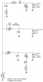
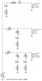
I experimented with different topologies to achieve best compromise of your tips and my design goals. Using VituixCAD makes this process so much faster and can be addictive
") .
.Didn't hear and measure R2 yet. I am waiting for x-over parts.
Attachments
Regarding post 2758: now what is the magic trick to avoid the "waistbanding" @1.5kHz? Trial and error with different slopes and some experimenting with x/o frequencies?
2748? One or more from the following:
1) Tweeter (wave guide) much less directive at XO than woofer.
2) c-c distance ca. 1.2 x wave length at XO.
3) Box shape to decrease directivity at XO and increase directivity octave above XO (smoothly with diffraction without sharp edges).
4) Phase match octave above XO and possibly clear mismatch octave below XO.
Items 1-3 are implemented in proper 2-way design. This is very rare in practice in my opinion.
manually entered 806x860 px.
Ok, that was final size of all six.
Your impedance compensation C+R might send some smoke signals. Check power dissipation or take it out if power amp does not care about jumps and rising trend of impedance response.
Ok, that was final size of all six.
Your impedance compensation C+R might send some smoke signals. Check power dissipation or take it out if power amp does not care about jumps and rising trend of impedance response.
Yes, it is getting pretty hot, even though R is 10W. I will order 20W.
Hi All,
I just been using Vituixcad for a little while. I was used to work with Lspcad, but the maker of this piece of software has made a very decent programm.
I am wondering if it`s possible to use in a 1 or 2 clicks action, to load one of the overlays in the calculator screen?
Is it also possible to let show the impulse windows in front of the rest of the 6 trace screens?
Grtz. Marcel
^Saving an overlay is two clicks. Loading overlay from external file is drag&drop.
Impulse and step responses are part of much larger feature which produces coefficients for FIR filter. I don't like to double anything with some limited default settings into main window which is already very full. Just keep IR window open while adjusting XO. Buy bigger display it not enough room. For example modern 27" is able show four VituixCAD main windows at the same time without overlapping.
Impulse and step responses are part of much larger feature which produces coefficients for FIR filter. I don't like to double anything with some limited default settings into main window which is already very full. Just keep IR window open while adjusting XO. Buy bigger display it not enough room. For example modern 27" is able show four VituixCAD main windows at the same time without overlapping.
kimmosto,
In the SPL and GD & Phase windows it is possible to disable the display of driver graphs. It's good. When there are more than two graphs, they interfere with seeing the changes in the resulting graph. But when I switch variants (R1-R8) to compare the resulting graphs of different variants, the driver graphs are turned on again. Is it possible to make the graphs that I disabled do not appear until I enable them?
In the SPL and GD & Phase windows it is possible to disable the display of driver graphs. It's good. When there are more than two graphs, they interfere with seeing the changes in the resulting graph. But when I switch variants (R1-R8) to compare the resulting graphs of different variants, the driver graphs are turned on again. Is it possible to make the graphs that I disabled do not appear until I enable them?
2748? One or more from the following:
1) Tweeter (wave guide) much less directive at XO than woofer.
2) c-c distance ca. 1.2 x wave length at XO.
3) Box shape to decrease directivity at XO and increase directivity octave above XO (smoothly with diffraction without sharp edges).
4) Phase match octave above XO and possibly clear mismatch octave below XO.
Items 1-3 are implemented in proper 2-way design. This is very rare in practice in my opinion.
I am sorry to restate what you have written, but I want to be sure I am understanding your advice,
1) Waveguides are good, they make the tweeter less directive at XO than the woofer.
2) Usually I try to make the tweeter and woofer as close together as possible. Are you saying there is a specific formula for spacing? And that maybe closer isn't always better?
"c-c distance ca. 1.2 x wave length at XO."
Could you expand on this?
an XO of 1500hz is a wavelength of 9", x1.2 is 10.8". That seems very far apart.
3) Just your regular roundover or chamfer, the larger the better.
How different are roundovers vs. a chamfer?
Can you model chamfers with the diffraction tool?
What about square edges around the woofer and large "facets" cut around the tweeter instead of the larger roundovers/chamfer?
4) That is up to the XO...
Thank you,
David.
Last edited:
Hello DaveFred,
Just to encourage you: you are asking all the question most of us are afraid to ask publicly. With the modest drivers at hand, i.m.o you have already done a job that is far beyond the standard focus on axis x/o design. Looking forward to see how/if this design could be improved even further. Keep on trucking!
Just to encourage you: you are asking all the question most of us are afraid to ask publicly. With the modest drivers at hand, i.m.o you have already done a job that is far beyond the standard focus on axis x/o design. Looking forward to see how/if this design could be improved even further. Keep on trucking!
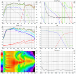
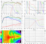
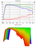
Top five responses have the same trend upwards from XO to 3.5 kHz. Result depends on what you listen, but any relative emphasis around 3 kHz is almost the worst case scenario. For example 80s' Iron Maidens having hump at ~3 kHz possibly due to monitors with BBC dip cannot tolerate any systematic mistakes.
In addition, you boost LF of tweeter with impedance peak of system resonance. That is not healthy action though wave guide helps in your case. There will be excursion peak at 1.15 kHz but 0.25 mm won't be exceeded with normal SPL. Unnecessary excursion causes extra IMD.
Some times these forums remind me of a quiz game show where you only can ask a couple of questions and then you have to guess the answer. I would love to have an in person conversation with you.
But I guess chatting on the forum will have to do.I am perfectly fine with unlearning "old" mistaken ways of doing things and learning "new" (better, more correct) ways to do things.
One thing I had always strived for was a flat on axis response, but after listening to Mr. Toole (a fellow Canadian BTW) about room response, reflections and the Spinoramma is why I went to the effort of building an automated turntable, buying Arta and trying to learn more than "on axis".
I spent a good part of the afternoon looking a speaker measurements over on the Audio Science site and noticed most had "waistbanding" issues at the crossover point, so I guess that is something that just has to be lived with. Each had various bundling and null issues at the XO point.
What "goals" would you suggest a crossover should have, i.e. what would would an ideal (realistic) crossover result look like in the SPL and Power & DI windows look like?
---
One very specific question is about, In Room Response, Power Response, Early Reflections vs. on axis SPL.
Is there a rank of importance?
Should on axis be made flat at the expense of In Room Response? Or vice versa?
If Room Response & Power Response are the goal and if the on axis has a dip or peak (especially off axis peaks) outside the target SPL, that's the way it needs to be?
---
While I know the drivers from my current project are less than ideal, can you make some suggestions about what characteristics to look for in drivers, especially for a two way?
As always, thank you,
David.
1) Waveguides are good, they make the tweeter less directive at XO than the woofer.
Possibly but not necessarily. Wave guide is quite large - possibly too large in many modern speakers though large wave guide might be needed with shoe box enclosure. Equal directivity at XO causes hump to directivity index without significant (~90 deg) phase mismatch.
2) Usually I try to make the tweeter and woofer as close together as possible. Are you saying there is a specific formula for spacing? And that maybe closer isn't always better?
"c-c distance ca. 1.2 x wave length at XO."
Could you expand on this?
'As close as possible' could be 'the worst possible' for directivity index i.e. either on axis (~listening window) or power response or both should be compromised to get balanced sound.
Of course if minimal vertical lobing is priority #1 then you should locate as close as possible. Coaxial driver wins that game always, but otherwise not necessarily...probably.
With simplified theory c-c = 1/2 wave length is the worst case for power response with equal DIs, and c-c = wave length at XO is the best case. Simply because sum with difference of 1/2 wave length is null and vertical +/-90 deg have the biggest weight in power calculation (due to dual orbit data to spherical intensity conversion). Early vertical reflections have significance too and DI of different radiators are not always equal => the smoothest DI and ERDI is found when c-c = 1.0-1.4 x wave length. This means that possibility of the worst DI is when c-c = 0.5-0.7 x wave length.
c-c studies are ridiculously easy with VituixCAD. Just load measurement data of the radiators, create ideal flat on axis response (with Optimizer and G(f) blocks) with estimated XO and tune driver's Y mm until combination of DI and ERDI is the best.
3) Just your regular roundover or chamfer, the larger the better.
How different are roundovers vs. a chamfer?
Can you model chamfers with the diffraction tool?
What about square edges around the woofer and large "facets" cut around the tweeter instead of the larger roundovers/chamfer?
Quite many questions and I don't know what "facet" is.
I prefer rounded chamfers, 45 deg and R>=32mm, both quite easy to manufacture. Tweeter should have very small effective baffle size to create directivity above typical XO frequency.
Diffraction tool is limited, but supports designing flat baffle area so that directivity dips and humps due to edges compensate directivity dips and humps of drivers and estimated combination of them assuming phase match at XO. Few tips:
- Do not increase directivity at XO with the box because phase matched XO does it anyway.
- Do not increase directivity below XO with the box because woofer cone does it anyway.
- Increase directivity above XO with the box if tweeter does not have wave guide or wave guide is small.


I would love to have an in person conversation with you.
e-mail is okay and could be the only option in the future. I have had some plans to abandon diyaudio. Few reasons:
- Writing of really good answers takes too much to time. My mother's language is Savo - not English.
- Discussion is very polarized: perfectionists/scientists with their wavefront simulations and absolute beginners totally lost with XSim. I'm lost somewhere between.
- Frustration with recommending medieval measurement and design methods and tools.
- Sticky threads which support the previous guiding beginners to obscure or bad path imo.
- My partners in commercial audio do not like that I leak my acoustic design secrets and tools for free.
Facets, the triangles cut out of the upper corners around the tweeters, sometimes also done on the bottom corners around the woofer.
Ok, that's what I like do but with rounding. Problem is manufacturing cost.

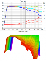
'Proof of concept' c-c = 1.2 x wave length at XO. Tweeter is TW030 i.e. no wave guide. Box with rounded facets.
Curious which of the ~10 30mm TW030's that is?
Search results for "TW030"
- Home
- Design & Build
- Software Tools
- VituixCAD