So the dip is because of the path length difference with vertical offset! I should have seen that.
but if I actually buy two of these 30" ribbons and stack them vertically I will have a gap between them which I can't model in a single 60" long ribbon but which theory suggests I might be able to ignore...
Maybe I should use 3 ribbons and shade the outer two.
Several things to think about. Thanks.
but if I actually buy two of these 30" ribbons and stack them vertically I will have a gap between them which I can't model in a single 60" long ribbon but which theory suggests I might be able to ignore...
Maybe I should use 3 ribbons and shade the outer two.
Several things to think about. Thanks.
^Three ribbons is one option to avoid possible problem due to narrow gap between two ribbons. But problem could be small - maybe fully acceptable in practice.
You can also improve simulation with Diffraction tool by creating tall radiator with one extra driver and then erasing the middle one.
Off-axis simulation with BesselJ1 and sinc functions is fast but unfortunately not accurate because formulas work to infinity. Calculation with multiple point sources (such as in The Edge) supporting near field is more accurate, but radically slower. I tested that once, but rejected due to poor performance.
confused! a vertical tilt fixes horizontal response?
Yes. Geometry is amazing isn't it
")
Please allow me a stupid question - how do I display the driver layout window? I just cannot find it. Are there any steps I need to do before it is possible to open it? I can change the positions below the crossover schematic, but cannot display the window. Thanks!
Edit: I tried right clicking at various places and I found it.
Edit: I tried right clicking at various places and I found it.
Last edited:
You can also improve simulation with Diffraction tool by creating tall radiator with one extra driver and then erasing the middle one.
But when I do this I have 50 driver limit and 30" or 60" or 90" to span so the individual elements are 18mm W x 36 mm tall and the frequency response has ripples just like a discrete array. This is not what I would expect from a continuous ribbon.
It seems to me I need to make a driver that covers 1/50th of the vertical span using diffraction tool and then instantiate 50 of them on the XO schematic, with gaps as needed. Is that my best plan?
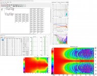
I got the highest resolution by modelling hierarchically. Each 30" ribbon is modelled as a stack of 16 18mm wide x 48mm tall blocks placed on the XO schematic. Each block is modelled as 48 1mm tall slices in the diffraction tool. This looks a little better and its more believable.

Attachments
frequency response has ripples just like a discrete array. This is not what I would expect from a continuous ribbon.
Continuous long ribbon has ripples too.
----
Tall straight radiator is "unstable" anyway because response shape depends on distance. This is quite unpleasant feature imo. Main reason why I don't dream about line arrays.
---
You have quite many LF drivers so simulation speed is already low. In order to speed up calculation and avoid problems in the main program due to two separate directive point sources, it's worth to create single long radiator with Diffraction tool, and export responses with Axis Distance = Listening distance in Options e.g. 4000 mm in both if you finally listen at 4 meters. After that off-axis angles in Diffraction tool are compatible with off-axis angles in the main program, and you have just one driver instance in crossover. Maybe with some extra ripples, but should be okay for preliminary study.
I can already see that long ribbon isn't a panacea.
I did hierarchical modelling - made a 48 mm segment in diffraction tool and placed multiples of these on XO schematic to model the tall ribbon which turned out to be when I found a photo 3 15" segments with 1.5" gaps; those gaps being large enough to affect response above 10 khz. Simulation speed is good enough; would be better on a faster machine or if your code could use multiple cores.
It now seems futile to me to pursue a speaker than is nearly as good standing as seated. Yes, Synergy perhaps comes close IFF very large horn. Shaded full range driver line array can be good (@wesayso). But you can't shade a continuous ribbon so have to optimize for seated. Even though shaded line array can be good for standing and better for seated. If you optimize for seated only, it gets even better
This is probably total off-topic, but speaker concept is not the key to good sound reproduction. Studying and building different designs, concepts, radiators, amount and type of directivity could be interesting hobby, but final solution comes with room acoustics. Shortening early delay time etc. until acoustic resolution reaches personal preference. No speaker concept is able to beat that. High quality components, construction and radiators without excessive directivity at HF to avoid spitting of artificial details.
2.0.60.0 (2021-01-15)
Main
* Rotate command moved from context menu to R button below schematic.
* Single component is possible to rotate with right click while dragging.
* Wire stretching while component movement is controlled with Stretch checkbox. Was earlier by pressing Alt-key while movement.
* Coordinate text boxes and zooming 1:1 and Fit buttons moved up a bit to make some room.
and radiators without excessive directivity at HF to avoid spitting of artificial details
can you give some examples of poor hf directivity?
^No names, but generally ring radiator, long planar/ribbon and horn requires very high quality driver to avoid spitting HF resonances to your face.
"Soft/damped" conventional metal dome with diffuser is not so directive requiring better room acoustics (=low EDT) for adequate acoustic resolution, but could also be higher quality due to low resonances at HF.
"Soft/damped" conventional metal dome with diffuser is not so directive requiring better room acoustics (=low EDT) for adequate acoustic resolution, but could also be higher quality due to low resonances at HF.
2.0.60.0 build 2021-01-16
Tiny adjustment to wire stretch mode: Pressing Shift key while dragging inverts wire Stretch mode on the fly. Status of Stretch checkbox is saved to user settings.
Now it's very close to original function (with Alt key) but enables selection of default mode.
Tiny adjustment to wire stretch mode: Pressing Shift key while dragging inverts wire Stretch mode on the fly. Status of Stretch checkbox is saved to user settings.
Now it's very close to original function (with Alt key) but enables selection of default mode.
Member
Joined 2003
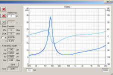
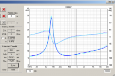
In the T/S parameter calculator, I seem to get inconsistent values for the extended Z model for semi-inductance. It seems to rely on the component values being near the expected value previous to hitting the "solve" button on the calculator. The curve can often be a fair bit off on the measured impedance, but hitting the solve button again doesn't get any closer. Starting from all parameters = 0 does not result in as good a result as if the parameters are manually adjusted somewhat.
It would be great, to allow manual adjustment of the extended Z model values, to help nudge the curve fitting algorithm in the right direction. As it is, I have to close out of the T/S calculator to change the values on the "edit parameters" window , then re-open the T/S calculator to see what the curve looks like and re-solve.
It would be great, to allow manual adjustment of the extended Z model values, to help nudge the curve fitting algorithm in the right direction. As it is, I have to close out of the T/S calculator to change the values on the "edit parameters" window , then re-open the T/S calculator to see what the curve looks like and re-solve.
Member
Joined 2003
Member
Joined 2003
Here, we started at all values for Le, Leb, Rss, Ke = zero. Error = 0.58 and you can see the values are very different than above. Hitting the solve button multiple times will never get to the error = 0.017 result above.
Attachments
Last edited:
- Home
- Design & Build
- Software Tools
- VituixCAD