I'm sorry Kimmo ") , I didn't mean to pose all of those questions to you directly. I just meant that those are the kind of questions I want to use VCAD to answer before committing money to a purchase.
, I didn't mean to pose all of those questions to you directly. I just meant that those are the kind of questions I want to use VCAD to answer before committing money to a purchase.
Regarding horizontal-to-vertical mirroring, ok, I see. That makes sense. As long as it was on purpose and not a bug.
Thanks again!
, I didn't mean to pose all of those questions to you directly. I just meant that those are the kind of questions I want to use VCAD to answer before committing money to a purchase.Regarding horizontal-to-vertical mirroring, ok, I see. That makes sense. As long as it was on purpose and not a bug.
Thanks again!
^I know that questions were not direct, but answers tried to tell that e.g. tracing of responses to half space is not mandatory to get an answer for those questions. Just some basic theory about sensitivity and baffle loss, and experience with properly designed projects to show what is important and what (/how much) you can not control with too simple acoustical simulations before buying components and building a prototype.
I am trying to use VCAD to choose a midrange and tweeter that have "compatible" dispersion patterns (smooth DI curve when properly crossed). With the caveat that I can fix FR problems with DSP/EQ as long as the problem is equal across dispersion. Ie, I look for smooth normalized off-axis FR measures at HiFiCompass, et al.
Once drivers are chosen, I will design DSP config empirically. No simulation needed (use sim as a starting point though).
Not a good plan? Or not the intended purpose of VCAD?
Once drivers are chosen, I will design DSP config empirically. No simulation needed (use sim as a starting point though).
Not a good plan? Or not the intended purpose of VCAD?
Very quick change to handing of single response loaded for driver. Hopefully this will not cause any trouble.
2.0.57.6 (2020-11-19)
Main
* Single frequency response loaded for driver is handled as omni-directional for Power & DI calculation.
Nice !!!
Nice !!!
Yes. I think this is particularly helpful when pulling in the response from the Enclosure Tool for modelling sub-woofing (<80Hz is omni).
Single response of driver has been handled as omni-polar for some time, but limits of measured sector in power & DI calculation were not removed for this special case. Just one if-clause was required.
But my strategy has been that (single) simulated response to half space is not loaded directly from Enclosure tool to driver in the main program. Especially if the other drivers have also off-axis responses and user wish to see realistic smooth transition in off-axis, power and DI responses. Therefore there is no 'Feed to speaker' feature for frequency response. Just for impedance response.
Simulated response to half space should be loaded from Enclosure to Diffraction tool, which is able to create full space responses and load whole off-axis response set to main program with almost any angle step you like. Diffraction tool contains also floor reflection option which could be suitable for subwoofers close to floor, radiating to half space.
Last edited:
My free time is not very valuable because I don't have important projects at the moment, but my boss might think that we are wasting employer's money.
Another view could be that we all (writers and readers) are wasting our time if recommended design procedure is not followed. But that would be just an opinion. Everybody is free to follow own gurus, national traditions and philosophies no matter what I think and hope and how I design speakers.
Another view could be that we all (writers and readers) are wasting our time if recommended design procedure is not followed. But that would be just an opinion. Everybody is free to follow own gurus, national traditions and philosophies no matter what I think and hope and how I design speakers.
Not a good plan? Or not the intended purpose of VCAD?
Final off-axis responses depend on directivity of radiators including radiating surface, enclosure size & shape (in 3D), possible leaking ports/open back, location of radiators, crossover frequencies, slopes and phase matching.
If you trace manufacturer's measurements to 0,30,60 to half space or some IEC baffle or other known baffle or box, and use frequency responses in the main program directly or combined with simulated diffraction, you will not get correct off-axis responses. None of those responses without or with existing simulation features in VCAD provide accurate directivity result because simulated diffraction will not be accurate due to missing data (near field 90 deg) and too simple model in the simulation. Forecasting of spinorama without accurate diffraction data i.e. measurements of selected drivers in final or prototype cabinet is not very productive.
Proper method IMO is to design box size and shape to support directivity features of potential drivers, and select XO frequencies, slopes and phase matching to support combination previous two. You have several options in your game, and possibilities to compensate non-ideal features and compatibility of drivers with box shape and crossover.
and very quick repeat that directivity/spinorama does not define total quality of speaker so do not count everything on ideal directivity. Allow some tolerance and focus more to overall balance, dynamics, compression spectrum, subjective performance, resolution spectrum, room acoustics, speaker locations.
These two statements seem to contradict each other.
Distance from mic to DUT can vary by up to 5mm.
But, distance from mic to DUT is especially important with dual channel measurement.
Why doesn't up to 5mm matter?
Accuracy requirement depends on the highest XO frequency. Max 5 mm error is usually okay.
It matters especially with dual channel because differences in travel distance is saved to phase responses.
Distance from mic to DUT can vary by up to 5mm.
But, distance from mic to DUT is especially important with dual channel measurement.
Why doesn't up to 5mm matter?
Single channel mode is (almost) blind to sound flying time so it's not capable to measure distance differences. We can also say that distance errors do not matter (much).
Dual channel mode is able to measure sound flying time and distance differences so user should take care that error in mechanical distance from DUTs to mic stays as constant as possible (or known for compensating time offsets). I cannot require absolute zero tolerance from anybody because it's not possible in practice. Remaining error in magnitude and phase responses depend on crossover frequency and c-c distance. Error in power response is small assuming c-c ~ wave length so user should focus to distance error especially while measuring responses within listening window.
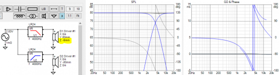
Example with acoustical LR24 crossover at 4 kHz. Timing error in upper driver is -5 mm. Magnitude error in axial is no more than 0.2 dB which may not have any effect to simulation producing component values. Error increases with higher XO points, and decreases with lower XO points.
Dual channel mode is able to measure sound flying time and distance differences so user should take care that error in mechanical distance from DUTs to mic stays as constant as possible (or known for compensating time offsets). I cannot require absolute zero tolerance from anybody because it's not possible in practice. Remaining error in magnitude and phase responses depend on crossover frequency and c-c distance. Error in power response is small assuming c-c ~ wave length so user should focus to distance error especially while measuring responses within listening window.
Example with acoustical LR24 crossover at 4 kHz. Timing error in upper driver is -5 mm. Magnitude error in axial is no more than 0.2 dB which may not have any effect to simulation producing component values. Error increases with higher XO points, and decreases with lower XO points.
Attachments
I have two speakers Scan Speak 25W8565-0 and 25W8565-1. They must work in the same enclosure. With bass reflex. The crossover is parallel, the cutoff frequencies are approximately 90 Hz and 170 Hz. I want to learn how to work with the Enclosure Tool. Can someone create a project for these two speakers and give me the vxe file? I tried but failed to enter two different speakers.
2.0.58.0 (2020-11-25)
Main, Optimizer
* Total axial, power, driver's axial and filter response target could be frequency response file (txt/frd) or textbook response with tilt, high-pass and low-pass.
* Target response file is possible to scale, delay, invert, minimum phase and smooth 1/2, 1/3, 1/6, 1/12, 1/24 oct.
* TF button is able to export transfer function also for total axial response to reference angle or listening window. This enables single 'input channel FIR' with G(f) block to create ideal minimum phase response for multi-way with conventional XO.
* Separate driver's target response removed from SPL chart.
This is quite massive change to optimizer though it may look the same. Bad news is that target lines in older project files (vxp) are not read so user have to reconfigure targets and save the project.
Member
Joined 2003
Member
Joined 2003
Frequency response files are simple and can be viewed in any text viewer. 3 columns of space separated data for frequency, amplitude, phase. Open your FR data and have a look at it, or post the file directly here. There's 100 ways to "generate the FR" so it's impossible to determine what you're doing incorrectly without more information.
Last edited:
I must be generating the FR .txt files incorrectly. they always have flat response to 40khz.
What do you mean by "generating"? Program extrapolates loaded responses to full internal frequency range 5...40000 Hz with 1/48 octs. steps to enable and simplify all calculations. So flat up to 40 kHz (or up to Nyquist with DSP) is normal and okay if the highest octave of source response is flat.
- Home
- Design & Build
- Software Tools
- VituixCAD