If you are repositioning the microphone and or speaker to take individual driver measurements, how do you maintain the exact 1m distance between DUT and mic?
I don't use any fancy methods such as two cross-hair lasers or 1m rod with tripod. Just measuring tape. Distance is very easy to measure and adjust to -90 and +90 deg off-axis. The most annoying challenge is drifting/swinging of center point while rotation.
Accuracy requirement depends on the highest XO frequency. Max 5 mm error is usually okay.
Or with dual channel measurement it doesn't matter if the distance changes?
It matters especially with dual channel because differences in travel distance is saved to phase responses.
2.0.57.4 (2020-11-08)
Enclosure, Add/edit driver window
* Allowed entering fundamental T/S-parameters Rms, Mms, Cms and BL first, and let program calculate fs, Qms, Qes, Qts and Vas.
* Shift + OK calculates missing parameters (value=0) without closing the window.
* Ctrl + OK calculates fs, Qms, Qes, Qts and Vas by fundamental parameters Re, Rms, Mms, Cms, Sd and BL (with c=344.0 m/s, ρ=1.194 kg/m3) without closing the window.
* Fundamental parameters preferred when Crosscalc is checked.
2.0.57.3 (2020-11-03)
Main
* Comment text could contain several http-links separated with space or new line. All links are opened at once by single double-click. All links are truncated to max 50 characters.
* Comment text with http-link(s) could contain normal text before, between or after the link(s).
* Links are opened with desktop application if link text starts with application's name: for example "onenote:https://..." and Shift key is pressed while double-click.
2.0.57.2 (2020-11-02)
Main
* Link comment (http:// or https://) truncated to max 50 characters.
* Allowed to remove rows from frequency response list in Drivers tab.
2.0.57.1 (2020-11-02)
Main
* Comment text in XO containing a link opens by double-click.
I'm a complete noob and I'm sorry for stupid questions, but why the Qtc for the closed box is limited to 0,90 only with some drivers?

I want to pair TC9FD18 with a subwoofer and want to cut it very low near Fc of the response of the driver in the box, so I need the correct rise from the real Qtc of my box.
I want to pair TC9FD18 with a subwoofer and want to cut it very low near Fc of the response of the driver in the box, so I need the correct rise from the real Qtc of my box.
Last edited:
Ah, I told that I'm a noob.
My compartment for fullrange is only slightly oversized and I was going to stuff it heavily with glass wool anyway, so calculating it for Qtc of 0.90 and Qa of 4 wasn't a complete failure, but I'm glad that I've asked.
I'm just sorry that I've bothered you with such basic stuff.
Thank you for a such amazing software!! I can't believe that it's freeware. It looks definitely better than some commercial stuff that I've seen.
Last edited:
Parameters of the following drivers updated to online database by datasheet revisions May 18, 2020. Mechanical parameters (Rms, Mms, Cms, BL) changed from preliminary advanced to traditional T/S. Advanced electrical parameters (Le, Leb, Ke, Rss) updated from preliminary to final.
Scan-Speak 5F/8422T01
Scan-Speak 10F/4424G00
Scan-Speak 10F/8414G10
Scan-Speak 10F/8424G00
Scan-Speak 12M/4631G00
Scan-Speak 12MU/4731T00
Scan-Speak 12MU/8731T00
Scan-Speak 12W/4524G00
Scan-Speak 12W/8524G00
Scan-Speak 15M/4531K00
Scan-Speak 15M/4624G00
Scan-Speak 15M/8631G00
Scan-Speak 15W/4424G00
Scan-Speak 15W/4434G00
Scan-Speak 15W/4531G00
Scan-Speak 15W/8424G00
Scan-Speak 15W/8434G00
Scan-Speak 15W/8530K00
Scan-Speak 15W/8530K01
Scan-Speak 15W/8531K00
Scan-Speak 15W/8534T00
Scan-Speak 15WU/4741T00
Scan-Speak 15WU/8741T00
Scan-Speak 18M/4631T00
Scan-Speak 18M/8631T00
Scan-Speak 18W/4424G00
Scan-Speak 18W/4434G00
Scan-Speak 18W/4531G00
Scan-Speak 18W/4531G01
Scan-Speak 18W/8424G00
Scan-Speak 18W/8434G00
Scan-Speak 18W/8531G00
Scan-Speak 18W/8535-01
Scan-Speak 18W/8542-00
Scan-Speak 18W/8542-10
Scan-Speak 18W/8545-01
Scan-Speak 18W/8545K00
Scan-Speak 18WE/4542T00
Scan-Speak 18WE/8542T00
Scan-Speak 18WU/4741T00
Scan-Speak 18WU/4747T00
Scan-Speak 18WU/8741T00
Scan-Speak 18WU/8747T00
Scan-Speak 21W/8555-10
Scan-Speak 21WE/4542T00
Scan-Speak 21WE/8542T00
Scan-Speak 22W/4534G00
Scan-Speak 22W/4851T00
Scan-Speak 22W/8534G00
Scan-Speak 22W/8851T00
Scan-Speak 22W/8857T00
Scan-Speak 23W/4557T00
Scan-Speak 23W/4557T02
Scan-Speak 25W/8565-00
Scan-Speak 26W/4534G00
Scan-Speak 26W/4558T00
Scan-Speak 26W/4867T00
Scan-Speak 26W/8534G00
Scan-Speak 26W/8861T00
Scan-Speak 26W/8867T00
Scan-Speak 28W/4878T00
Scan-Speak 28W/4878T01
Scan-Speak 28W/8878T01
Scan-Speak 30W/4558T00
Scan-Speak 32W/4878T00
Scan-Speak 32W/4878T01
Scan-Speak 32W/8878T01
") . Can you tell me what I have done to seemingly disable DI calculation?
. Can you tell me what I have done to seemingly disable DI calculation?


^Problem is somewhere else than in XO (though you have unnecessary wires between active blocks, PEQ at 39.6 Hz for tweeter and tweeter is not in the origin of speaker).
Most common mistakes are:
- File naming is not valid at all or was not compatible with settings in Options:Angle parsing from filename when files were loaded.
- All drivers listed in Drivers tab do not have response files for full 0-180 deg off-axis sector (or 0-90 deg for half space application).
- Response interpolation is on and drivers don't have adequate off-axis responses (and drivers are not at the origin 0,0,0).
- Driver instance in XO is not linked to response data in Drivers tab (this is probably okay is your case).
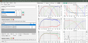
I think more helpful screenshots are lists of frequency response files:
and Options window:
Measurement instructions should help with file naming.
Most common mistakes are:
- File naming is not valid at all or was not compatible with settings in Options:Angle parsing from filename when files were loaded.
- All drivers listed in Drivers tab do not have response files for full 0-180 deg off-axis sector (or 0-90 deg for half space application).
- Response interpolation is on and drivers don't have adequate off-axis responses (and drivers are not at the origin 0,0,0).
- Driver instance in XO is not linked to response data in Drivers tab (this is probably okay is your case).
I think more helpful screenshots are lists of frequency response files:
An externally hosted image should be here but it was not working when we last tested it.
and Options window:
An externally hosted image should be here but it was not working when we last tested it.
Measurement instructions should help with file naming.
Hi Kimmo--
I cut down my schematic for debug, to just the tweeter. Here is what I found.


I cut down my schematic for debug, to just the tweeter. Here is what I found.
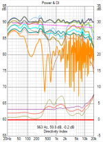
- When I uncheck "Listening window DI", the DI curve goes flat. I don't think this should happen. (I do think that I want to have that option checked going forward though)
- I did have a bug, but I don't think it was of my own making. My subwoofer FRD imported as -4* horizontal. I created the FRD by exporting it from the Enclosure Tool. So I have now set that to 0* manually in the Drivers tab.
With frequency responses to three directions only (0, 30, 60 deg) accuracy is probably better with Options:
- Interpolate unchecked
- Listening window DI unchecked
- Angle step 0 deg (measured directions only)
- Half space checked though it does not matter with previous settings.
These settings do not try to compose anything from close to nothing. Just use loaded data which is very poor in this case.
- Interpolate unchecked
- Listening window DI unchecked
- Angle step 0 deg (measured directions only)
- Half space checked though it does not matter with previous settings.
These settings do not try to compose anything from close to nothing. Just use loaded data which is very poor in this case.
Ok. I will try. But I think it is important to assume that people will do simulations from data sheet (using your excellent tracer!). I can't buy all the drivers I'm considering, mount to IB and measure. I like to simulate from the data I can find, which is not always complete.
It would be very nice if VCAD were full functional with data just to 60* since that is what is usually easily available. It could be Spinorama-lite in that mode.
With your recommended settings, I am getting a flat DI (it's always flat when I uncheck Listening window DI).
It would be very nice if VCAD were full functional with data just to 60* since that is what is usually easily available. It could be Spinorama-lite in that mode.
With your recommended settings, I am getting a flat DI (it's always flat when I uncheck Listening window DI).

Software is functional with 0,30,60 deg off-axis, but those three responses should be loaded for ALL DRIVERS listed in Drivers tab in order to get power and DI results. Not just for middle and tweeter or whatever added to crossover schematic. I think this is also mentioned in measurement instructions or user manual.
In theory I could handle single response as omni, but it's not implemented that way for power & DI response calculation.
Here is one of my sample projects with 0+30+60 deg only.
In theory I could handle single response as omni, but it's not implemented that way for power & DI response calculation.
Here is one of my sample projects with 0+30+60 deg only.
Attachments
Last edited:
I think it is important to assume that people will do simulations from data sheet... I can't buy all the drivers I'm considering, mount to IB and measure. I like to simulate from the data I can find, which is not always complete.
I have traced manufacturer's measurements for preliminary design just once within last 35 years. That was one the most unsuccessful projects in my history. Drivers were purchased and cabinets manufactured believing that traced data, woofer simulation and preliminary XO design tell something that I could trust. But manufacturer's measurement from compression driver and horn was total B.S. Almost anything is possible as active with DSP - with or without tracing, but passive filter was selected for that project.
Typically compatibility of drivers; USPL with baffle loss and directivity is possible to estimate without tracing. Just by looking data assuming that it's reliable. Some verification from multiple information sources is needed e.g. measurements available in the internet.
Accurate diffraction simulation would need traced response to 90 deg off-axis which is not available. Diffraction simulation with simulated piston directivity is not accurate enough for power & DI calculation. Simulated baffle loss to 0-90 deg or 0-180 deg could be okay, but it's not adequate for crossover design without measurements in final cabinet. Accurate timing differences are also not available with traced responses. Summary is that tracing is not needed, and it's too unreliable and inaccurate.
Last edited:
Very quick change to handing of single response loaded for driver. Hopefully this will not cause any trouble.
2.0.57.6 (2020-11-19)
Main
* Single frequency response loaded for driver is handled as omni-directional for Power & DI calculation.
Enclosure
* PR filter is disabled when project is opened to enable immediate calculation of active radiator.
* Driver configuration group is disabled when PR is selected from driver list.
You da man Kimmo!
I'm still sorta new at this, so please don't hesitate to educate me when needed!
I'm trying to use pre-purchase simulation to answer questions like: Do I need a tweeter with a bit of horn loading to best match the off-axis response of this 5" midrange. Or should I be using a 4" midrange instead? Should I really go 5-way?? (4-way + SW) Etc, etc. I'm trying to squeeze as much juice out of the pre-purchase lemon as I can. I can't just order up 8 $150 drivers and measure them all and start experimenting (would be nice, but...). So I'm getting as much as I can out of HifiCompass, AudioXpress (some of Vance's tweeter measurements are suspect IMO), AudioExcite, etc. And spec sheets if all else fails. So I'm trying to figure out the best way to use the incredibly good VCAD to chase the various Spinorama DI waves.
What about the display of horizontal dispersion when I selected vertical, and there were no vertical inputs to the driver, except 0*?
Thanks Kimmo!
--Myles
- Do I need a tweeter with a bit of horn loading to best match the off-axis response of this 5" midrange.
- Should I be using a 4" midrange instead?
- Should I really go 5-way?? (4-way + SW)
One answer to all questions (without knowing details) is 'not necessarily'. World is full of 5"+1" and 6"+1" without wave guide or horn. Some are very good and some are not. Wave guide/horn can also ruin axial sound regardless of better measured off-axis.
Proper methods and tools enable very good result also with slightly oversized mid-woofer. Worth to remember that ideal directivity visible in spinorama does not define total quality: is speaker "just good" or very good and enjoyable to listen. Some drivers sound better and some worse, and better driver with slightly worse directivity and power balance could be significantly better. So buying and listening is also possibility to find an excellent product.
I don't prefer subwoofers so 4-way is maximum for me.
What about the display of horizontal dispersion when I selected vertical, and there were no vertical inputs to the driver, except 0*?
Basic guidelines for skipping vertical measurements is explained in measurement instructions, but finally this depends on motivation (laziness) of designer. I usually mirror measurement data from horizontal to vertical with circular radiators located to vertical center line of cabinet. Rectangular, elliptical and non-centered should be measured in both planes.
Last edited:
- Home
- Design & Build
- Software Tools
- VituixCAD