Calculator has own output directory setting which is saved to user.config. Not to any project file because Calculator does not have projects.
Merger, Enclosure and Diffraction have project files. Merger saves output directory to vxm file. Enclosure and Diffraction tools ask destination while saving.
Merger, Enclosure and Diffraction have project files. Merger saves output directory to vxm file. Enclosure and Diffraction tools ask destination while saving.
Me again ")
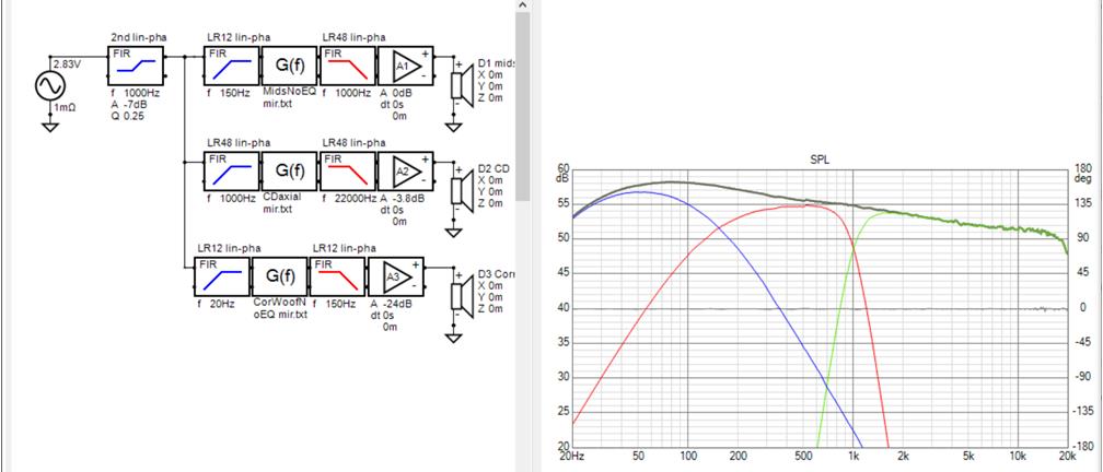
I'm implementing a crossover in JRiver so I need to create IR.wav files for the filters. I've made the filters in Vituix by using the mirror function of the calculator in a G(f) block to flatten a smoothed driver measurement followed by high pass and low pass filter blocks to establish roll off at each end of the range. That gives me a textbook perfect crossover in minutes, although I have to be careful not to make too detailed a correction.
I can export filter frequency response but I can't find a way to export a filter impulse response or convert the FR to IR and then export. Would it be possible to add that to Vituix? That would allow me to do keep the entire process except for the measurement itself in Vituix.
Thanks,
Jack
I've made the filters in Vituix by using the mirror function of the calculator in a G(f) block to flatten a smoothed driver measurement followed by high pass and low pass filter blocks to establish roll off at each end of the range.
Maybe you've already received some instructions from Draki for this. At least he has inbox quite full of instructions and discussion how to create filter transfer function files for FIR convolution.
Main thing is that this functionality is already done to small TF button in top left corner of Optimizer window so Mirror function in Calculator tool is not needed and recommended. User manual tells quite shortly:
"Driver's target response divided by response to reference angle can be exported with TF button in top left corner. Response file is loaded into Transfer function file G(f) block currently selected in crossover. This could be helpful while designing FIR filters with exported impulse response files because crossover can include single G(f) block and active buffer for each driver/way, and response is shaped automatically to ideal textbook curve with tilt given or detected from total SPL target line."
First you need to load frequency responses of drivers to Drivers tab. Smooth by 1/12 oct. Then create simple XO with single G(f) block and single Buffer block for each driver (or way). Open Optimizer, select "Axial response of driver" and driver from combo box on the right. Create driver's target response. Note that high pass of woofer should be minimum phase and low pass should be linear phase to create minimum phase multi-way speaker. Then select G(f) block in the XO and export filter response with small TF button.
Repeat the same for mid and tweeter with multi-way.
Add extra EQ block(s) between G(f) and Buffer to make compromise between axial and power responses if needed.
Finally export impulse responses of Buffer outputs or Driver inputs as wav files with Impulse response window.
Note that high pass of woofer should be minimum phase and low pass should be linear phase to create minimum phase multi-way speaker.
linear
^Linear-phase speaker would have flat 0 deg phase response from 20Hz-20kHz despite of woofer's HP slope at LF. That is not recommended because it's not natural and wastes FIR taps.
Minimum-phase speaker has minimum phase LF due to woofer's HP slope, and flat 0 deg phase response above that if magnitude response is flat. So previous method produces minimum-phase speaker (with help on linear phase crossover).
Minimum-phase speaker has minimum phase LF due to woofer's HP slope, and flat 0 deg phase response above that if magnitude response is flat. So previous method produces minimum-phase speaker (with help on linear phase crossover).
Thanks for those tips. I hadn't paid any attention to optimizer because I assumed (shame on me) it was for passive XOs. I built XO using methods familiar from other tools, which Vituix makes easier. But now that I'm aware of it I will try it out.
I can't complain about my results though. I invert the driver impulse response with mirror, then add filters to restore high pass and low pass slopes as desired, similar to target creation process. I'm sure the optimizer does as well with amplitude response, not sure what its phase result will be, or if it matters. I'll second what you say about minimum phase for the woofer low end roll off for natural sound although I used linear phase here without thinking about it.
I keep the room curve as a separate global filter block so I can tune it in real time using a plugin.
This XO is for my Synergies. I struggled through many iterations 4 years ago to first create and then optimize the XO using manual IIR in MiniDSP and in-room measurements. I took some of those old measurements and created this in minutes targeting Motu soundcard with Sabre DACs and Jriver convolution. I cheated though and I will have to get the delays for time alignment from my old XO. I see Vituix includes a time align function, something I struggled with initially in the Synergies. I tried the method Vituix uses but ended up using method based on aligning driver IR starts with XO filters in place. I haven't listened yet as the Synergies were set aside when I got interested in line arrays.
You don't recommend mirror over the optimizer but I do want to experiment with impulse inversion on my Synergies to see if it can correct for mouth and offset driver reflections while retaining a wide sweet spot.
Attachments
Maybe you've already received some instructions from Draki for this. At least he has inbox quite full of instructions and discussion how to create filter transfer function files for FIR convolution.
Main thing is that this functionality is already done to small TF button in top left corner of Optimizer window so Mirror function in Calculator tool is not needed and recommended. User manual tells quite shortly:
"Driver's target response divided by response to reference angle can be exported with TF button in top left corner. Response file is loaded into Transfer function file G(f) block currently selected in crossover. This could be helpful while designing FIR filters with exported impulse response files because crossover can include single G(f) block and active buffer for each driver/way, and response is shaped automatically to ideal textbook curve with tilt given or detected from total SPL target line."
First you need to load frequency responses of drivers to Drivers tab. Smooth by 1/12 oct. Then create simple XO with single G(f) block and single Buffer block for each driver (or way). Open Optimizer, select "Axial response of driver" and driver from combo box on the right. Create driver's target response. Note that high pass of woofer should be minimum phase and low pass should be linear phase to create minimum phase multi-way speaker. Then select G(f) block in the XO and export filter response with small TF button.
Repeat the same for mid and tweeter with multi-way.
Add extra EQ block(s) between G(f) and Buffer to make compromise between axial and power responses if needed.
Finally export impulse responses of Buffer outputs or Driver inputs as wav files with Impulse response window.
Looks like I need optimizer to improve results with limited number of taps...
I hadn't paid any attention to optimizer because I assumed (shame on me) it was for passive XOs.
TF button uses drivers' target responses but not optimizer algorithm. Export of transfer function for G(f) block was earlier in File->Export but it was inconveniently far from driver targets. Feature was moved in rev. 2.0.47.3 (2020-04-12).
These were done almost a week ago but too busy to upload.
2.0.51.5 (2020-06-22)
Main program
* Added separate absorption to Room tab for walls, ceiling and floor.
* Program remembers status of 'Show Target line' of SPL and Power & DI charts.
* 'Show Normal phase' and 'Show Normal GD' set on by default.
* File->Recent list automatically cleaned from project files which are not found anymore.
Thanks for the absorber change.
Re' TF button
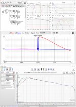
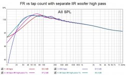
After I got the hang of it, I was able to get better results using TF mostly from working on woofer time alignment but it didn't help with tap requirements.
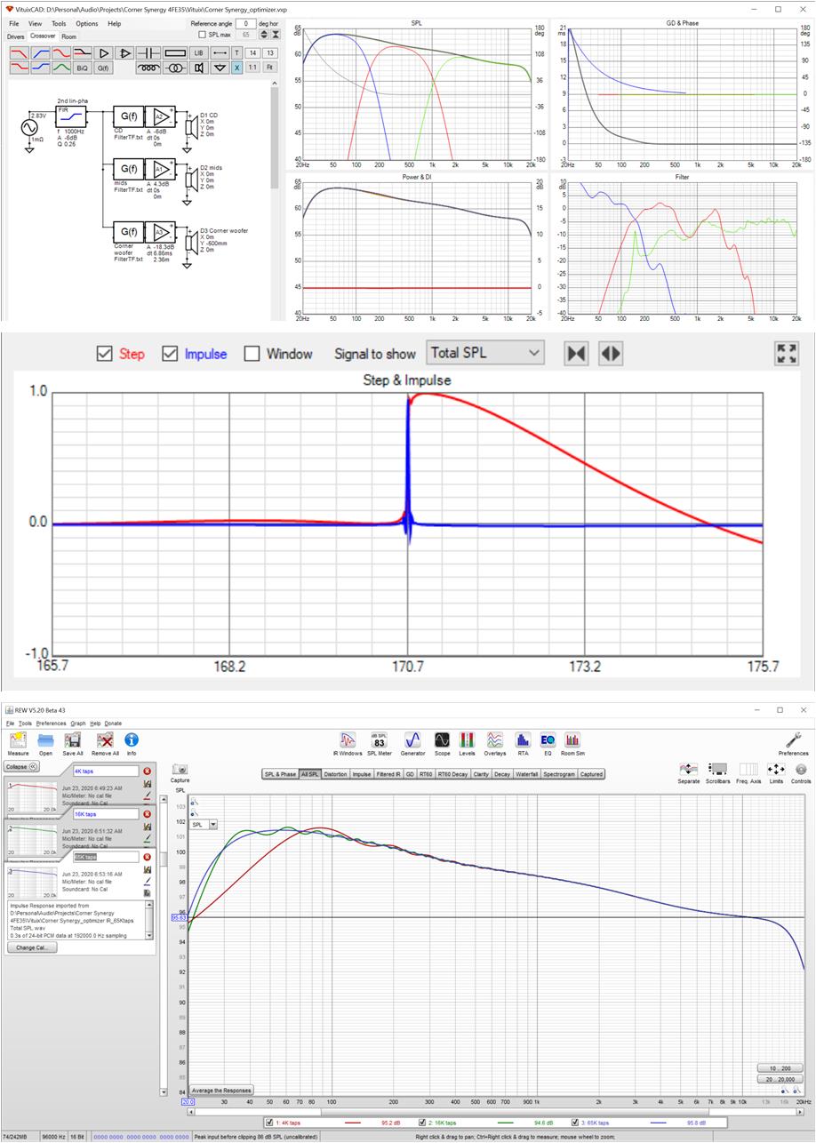
I imported IR(taps) into REW to evaluate. Doing this, I couldn't help but think how nice it would be if there were an (Save as Overlay) button right above the export button on the IR screen. The finite tap count FRs are plotted at 2 db per division so the error is not as bad as it looks
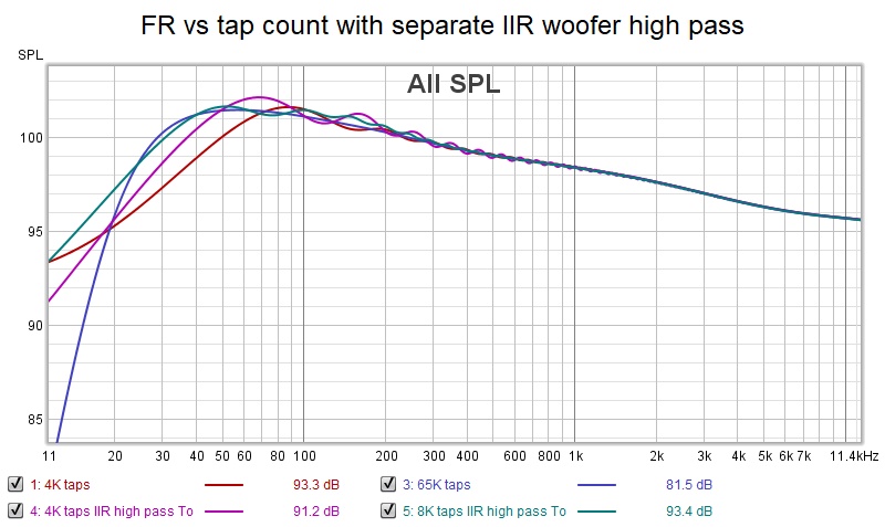
Taking the woofer high pass filter out of the G(f) and into a separate IIR block brought me about 1 db closer to the 65K tap curve in the 20-40 Hz region with 4K taps. 4K taps aren't quite enough; 8K looks great.
Re' TF button
After I got the hang of it, I was able to get better results using TF mostly from working on woofer time alignment but it didn't help with tap requirements.
I imported IR(taps) into REW to evaluate. Doing this, I couldn't help but think how nice it would be if there were an (Save as Overlay) button right above the export button on the IR screen. The finite tap count FRs are plotted at 2 db per division so the error is not as bad as it looks
Taking the woofer high pass filter out of the G(f) and into a separate IIR block brought me about 1 db closer to the 65K tap curve in the 20-40 Hz region with 4K taps. 4K taps aren't quite enough; 8K looks great.
Attachments
Hello Kimmo,
Firstly, thank you for the great software.
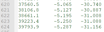
Can you extend the upper frequency of exported curve in the SPL tracer tool above 40kHz ? I need to digitizes a calibration curve of my mic which goes up to 100kHz. SPL tracer tool traces it ok up to 100kHz, but when I export the traced curve to txt file the highest frequency is 39793.9Hz.
Thank you.
Firstly, thank you for the great software.
Can you extend the upper frequency of exported curve in the SPL tracer tool above 40kHz ? I need to digitizes a calibration curve of my mic which goes up to 100kHz. SPL tracer tool traces it ok up to 100kHz, but when I export the traced curve to txt file the highest frequency is 39793.9Hz.
Thank you.
Attachments
Last edited:
^Images do not load and show. Try to use some other method to deliver information.
Sorry, the picture was not uploaded by pasting in edit mode.


Hello Kimmo,
The more I use VituixCAD, the more I'm impressed by this software. Very regular updates, so many functions and just to name one: Convert IR to FR justify by itself a five star rating !
I'm wondering if it is possible to implement the Hypex Fusion FAXXX dsp filters in a future update ?
Time for me to make a donation
Thanks again for this piece of freeware software
Best regards
Jean Claude
^I haven't asked documentation for biquad coefficient calculation from Hypex since February 2019. Answer was this:
HFD uses some frequency warping compensation, but finding it by guessing or iterating is not so easy for me. Result with warping compensation is quite close to ideal textbook and usable with "overclocking" workaround imo. Not exactly accurate though.
Not so long time ago when I tested possibilities to add response support also for Lake LM DSPs. They have quite special (far from common biquad DSP standards) filter transfer functions so that was totally hopeless.
Hello Kimmo,
Our software uses some proprietary calculations but unfortunately they are not documented.
Kind regards,
**** | Hypex Electronics BV | Technical Support Engineer
HFD uses some frequency warping compensation, but finding it by guessing or iterating is not so easy for me. Result with warping compensation is quite close to ideal textbook and usable with "overclocking" workaround imo. Not exactly accurate though.
Not so long time ago when I tested possibilities to add response support also for Lake LM DSPs. They have quite special (far from common biquad DSP standards) filter transfer functions so that was totally hopeless.
Thanks for the fast answer.
I have 3 pair of FA plates for different projects but I scratched my head regularly with their software (to say the least) so I have switched now to VituixCAD with the generic dsp option and refine filters with further measurements. It would have been so simple with Hypex collaboration...
I have 3 pair of FA plates for different projects but I scratched my head regularly with their software (to say the least) so I have switched now to VituixCAD with the generic dsp option and refine filters with further measurements. It would have been so simple with Hypex collaboration...
- Home
- Design & Build
- Software Tools
- VituixCAD