Few basic rules for linking XO of driver in the main program and driver+enclosure system in Enclosure tool:
* Accurate extended impedance model of driver is mandatory in Enclosure tool if crossover in the main program is passive or semi-passive. Default impedance model with Re+Le only damages transfer function of XO because it's usually very far from fact.
* Number of drivers in Enclosure tool must be one (1) because main program feeds transfer function of single driver to radiator simulation in Enclosure tool. Box and possible vent should be scaled for single driver. Drivers having different filter in the main program should be investigated separately.
* Impedance response loaded from Enclosure tool back to main program is not saved to project file. It's just temporary trick in memory -> no need to be afraid that project is damaged. Original impedance response in zma file loaded to Drivers tab can be restored by changing impedance scale to 1.05 and back to 1.0. Until something is changed in Enclosure tool.
* Link between crossover in the main program and enclosure tool is contrived. I hope that users could design speakers without it.
Zip also enclosure project if you send something.
I have resistors in XO for weighting - explains the mysterious response change with enclosure tool via default vs actual impedance curve.
Not sure what I had number of drivers set to as it is an array. will check later and respond
I can certainly design speaker w/o enclosure tool but I will have more confidence in my design if it can crosscheck my maximum SPL estimation
Thanks
See what?
*** This...
"...ower dissipation window is one option in VCAD because it's able to show current and voltage of each driver...
^In Power dissipation window - as I told")
***As they say in Russia "I didn’t understand anything, but it’s very interesting"
Ок!
I continue to study your program!
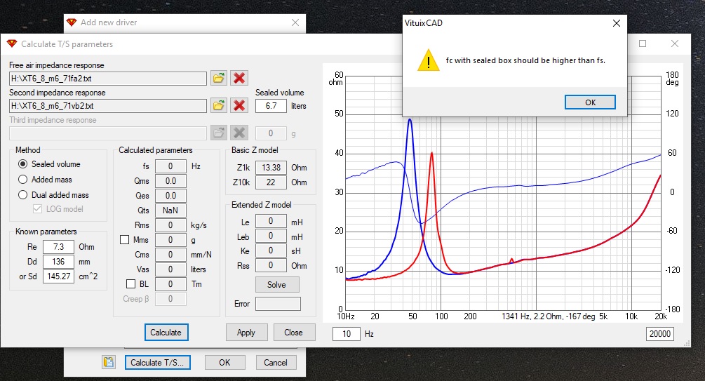
It seems the T/S calculation function may be broken.
All files work here so it's just sensitive to some noise or extra resonances in your files. Could you send problematic files to my e-mail that I could make some filtering or double scanning to focus correct peak?
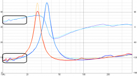
^Impedance response measurements are very bad within 10...14 Hz. That quality would be impossible e.g. for dual added mass method. Try to reduce noise or mechanical resonances especially at LF (stepping frequency, environment noise down, mechanical resonances damped, ...). Single added mass and sealed volume are not so sensitive and T/S extraction is possible with the following workarounds. Risk is that some other functions in the program are now worse / less accurate due to wider range for slope detection at LF.
The latest build of rev. 2.0.50.0 (2020-05-04) includes:
Calculate T/S parameters
* Impedance responses extrapolated at LF by the first 1/3 octave to avoid errors due to noisy measurement.
* Impedance responses read for fs and Qm detection where Z > Re x 1.5 to avoid errors due to noisy measurement.
^Sample rate, bit depth and lowest frequency are not so relevant. Measurement signal, silence of environment and robust mechanical connection of the driver and added mass are more important. Steady state stepping sine is good. Very fast sweep or MLS or white periodic are not.
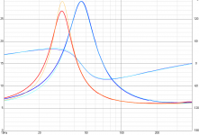
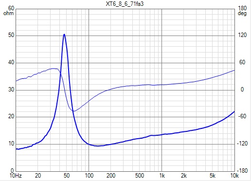
Two examples. The second one is measured with Smith & Larson Woofer Tester Pro (WTPro) at Seas, steady-state sine wave signal which is stepped 384 times in the frequency range 10 Hz...20 kHz.
Two examples. The second one is measured with Smith & Larson Woofer Tester Pro (WTPro) at Seas, steady-state sine wave signal which is stepped 384 times in the frequency range 10 Hz...20 kHz.
Attachments
Does anyone know good video tutorial about this new updated program in full. Not just short clip with "stupid" electronic voice but normal tutorial for easier understanding how to work with it? From measuring speakers till assembling crossover with it? (not a guy with earsholes plz )
Yes,we can die by reading manual (very strange visually made) from official page.
Can be reduce significant amount of unnecessary questions and GURU nerves.
)Yes,we can die by reading manual (very strange visually made) from official page.
Can be reduce significant amount of unnecessary questions and GURU nerves.
^Sample rate, bit depth and lowest frequency are not so relevant. Measurement signal, silence of environment and robust mechanical connection of the driver and added mass are more important. Steady state stepping sine is good. Very fast sweep or MLS or white periodic are not.
Two examples. The second one is measured with Smith & Larson Woofer Tester Pro (WTPro) at Seas, steady-state sine wave signal which is stepped 384 times in the frequency range 10 Hz...20 kHz.
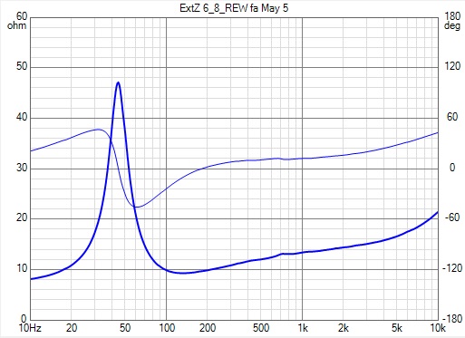
Thanks for this sanity check, Kimmo. SoundEasy doesn't seem to mind the noise. Nevertheless, I was able to improve (reduce) the noise by maxing out the sound card settings and only doing attenuation in the analogue domain. There was still some noise, though. I usually use 1/24 octave smoothing. I could get the curve much smoother in SE by going down to 1/6 or 1/3 octave, but it seemed to change the curve too much for my liking. SE uses MLS signal and it appears that I have reached maximum performance with this setup.
Best SE-measured curve with 1/24 oct smoothing:
I next redid my measurements with REW and the curves are smooth, like the ones you showed above. The hardware is the same; REW uses a frequency sweep.
REW-measured curve:
Has anyone used VCAD to design an analog active XO and successfully executed it ?
I am reading through the LX-Mini Crossover thread since I do not want to mix in yet another
DAC chip / stage after the primary DAC that I will use in my system.
I see that there are the OP-amp circuitry present in VCAD so I should be able to figure things out. Might end up using discrete JFet's rather than OP-amps.
when adjusting driver z value in the crossover tab the freq response drops out for the 60 deg off axis curves in the directivity graph when going beyond -10 mm
Dropping of the highest angle is unfortunate side effect if measurement sector is not either half space 0-90 deg or full space 0-180 deg and some driver is moved in front of rotation center (neg Z) and response interpolation is in use. The reason is that exit angle from driver to virtual microphone is outside measured sector so there's no data where program could interpolate.
Possible solutions are:
a) Uncheck Interpolate in Options window. Program uses the nearest measured angle without caring is it outside measured sector or not.
b) Move all drivers so much further from mic that exit angle will stay within measured sector. This could require 100...400 mm movement to avoid dropping also in vertical plane. This is not recommended.
c) Increase listening distance in Options window to 99900 mm to keep exit angle within 0.5 deg to all measured directions
d) Measure full sector in the future - as measurement instructions already ask you to do.
Equipment Recommendations
I'm a little puzzled about what sort of microphone, sound card, etc, I should use with VituixCAD. I see that USB mics are not recommended. But what would be good? I have seen the Dayton mic recommended, but what sort of sound card will work well? (I'm on Linux, but most sound cards work fine with it.)
I'm a little puzzled about what sort of microphone, sound card, etc, I should use with VituixCAD. I see that USB mics are not recommended. But what would be good? I have seen the Dayton mic recommended, but what sort of sound card will work well? (I'm on Linux, but most sound cards work fine with it.)
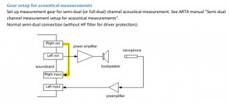
From Kimmo's Measurement with ARTA doc page 2
The most important to have is a two channel input (left and right), so you could create a loopback signal. this is what the USB mics are missing. This is the only reliable way to know the exact timing of playbac/record as you can't trust any of the OS-es to keep it constant... probably even with Linux.
Search for other threads in this or other forums. The soundcard selection has been covered tens of times. There are many many pro and semi pro soundcards that are suitable.
Attachments
a) Uncheck Interpolate in Options window. Program uses the nearest measured angle without caring is it outside measured sector or not.
that worked great, thank you
From Kimmo's Measurement with ARTA doc page 2
The most important to have is a two channel input (left and right), so you could create a loopback signal. this is what the USB mics are missing. This is the only reliable way to know the exact timing of playbac/record as you can't trust any of the OS-es to keep it constant... probably even with Linux.
Search for other threads in this or other forums. The soundcard selection has been covered tens of times. There are many many pro and semi pro soundcards that are suitable.
Thanks for the reply. I did try searching, but if you just search for "sound card" or "soundcard" you get 20K hits, and if you search for "sound card vituixcad" you get less than 20, none of which are helpful.
It would be nice to collect this information somewhere specific. It must be a frequently asked question.
I see things like the Focusrite Scarlett 2i2 mentioned often. But, as far as I can see, that's only for recording, not playing, and I'm not sure how I'd loop a line-level signal into it.
- Home
- Design & Build
- Software Tools
- VituixCAD