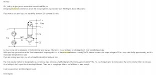
It seems to me that you are complicating a simple thing like a SMPS. All capacitances will be combined in one, reflected to the primary, that will became part of the resonant tank, together with the MOSFET's and diodes' capacitances. Also, surely you will need to add a fixed larger capacitor to ensure the highest frequency the SMPS can reach at lower loads, or driving the MOSFET's will be a problem and efficiency at low load will became a large headache.
It seems to me that you are complicating a simple thing like a SMPS. All capacitances will be combined in one, reflected to the primary, that will became part of the resonant tank, together with the MOSFET's and diodes' capacitances. Also, surely you will need to add a fixed larger capacitor to ensure the highest frequency the SMPS can reach at lower loads, or driving the MOSFET's will be a problem and efficiency at low load will became a large headache.
As I have seen, and read for low loads the controller go into skip mode or burst mode, that is the way a open output is done normally. But it did work also when play with the Lr/Lm ratio
For me I have to learn some more so I do this things because of that, I do not that the resonant tank is a whole setup of capacitances and inductions around it, the mosfet capacitances however do not that much, in calculation programs I do never see that I need to include them, for as what is needed, I have need more voltages and as such and no calculator I do play some around.
Hva now installed ultiboard dos, I go make a pcb and do experiment in real time, go make a protection for the high voltages first, a ground fault circuit breaker or such.
regards
I did after some reading and calculating have found the errors I did make, special when calculating turns ratio, I get myself whole other outcomes then with the excel sheets, first I did make a mistake with the power, this needs to be not higher then needed, circulation current was high, because of wrong setup, and Lm Lr and Q was not the right value.
I have read some papers where it is explaned quite good, and have mail one of the people behind who have also give a anwer about how to proceed.
As what people here said, just it is that resonant and smps in special cases, it is not that simple and potential dangerous.
I have to find ethe right formula,s to calculate the Np/Nsec because I do wrong, that is why when I do lowering the secondairy induction I can tune the feedback to work in all loads, if the Q and Ln are right, in mine case Q3 and Lm 6 as a test on 80, 180 Khz swing.
I did calculate transformer Lp : ratio Ls who did not was oke, get to high Lsec then .
I do use now the excel sheet who has multiply voltages.
regards
Attachments
Well, ok, it is interesting to read from those that know the thing very well. Continue posting the improvements.
This was his opinion to prove how complicated this can be, in sense of savety and good working. And he has experience with design, it is complicated resonant system, repeat designs is even difficult.
In fact when now,it is quite easy to understand, like it is a antenna 50 ohms on a transmitter the Q does set bandwidth.
Attachments
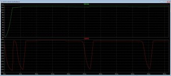
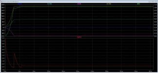
This sim did all oke, burst mode does work keeping no load stable. PIC 1 is unloaded and PIC 2 is loaded converter with all voltages. For 12.6volts and 6.3 volts I do need to split the coil what is in feedback, I do tap it from the 12,6 volt so it is also stable, how to that best way?
I did when search for reading find another LLC topology who does asymetric switching, and quite less loss and more stable, just a halfbridge in asymetric swithing patron. nice read.
http://dspace.kaist.ac.kr/bitstream/10203/215751/1/2016ECCE_정연호.pdf
I have need this feedback when feed tubes, the filament voltage needs to be good and stable, I need audio from it and not use it as a light bulb.
regards
Attachments
Last edited:
Accidentally I found those two interesting articles about the TL431:
https://www.google.com/url?sa=t&rct...cs_tl431.pdf&usg=AOvVaw335o8z-97HVAncPEJZ0g5F
and:
https://www.google.com/url?sa=t&rct...TND381-D.PDF&usg=AOvVaw3UEEYmpFQ9I7Sjpi3_qJgl
Enjoy!
https://www.google.com/url?sa=t&rct...cs_tl431.pdf&usg=AOvVaw335o8z-97HVAncPEJZ0g5F
and:
https://www.google.com/url?sa=t&rct...TND381-D.PDF&usg=AOvVaw3UEEYmpFQ9I7Sjpi3_qJgl
Enjoy!
Accidentally I found those two interesting articles about the TL431:
https://www.google.com/url?sa=t&rct...cs_tl431.pdf&usg=AOvVaw335o8z-97HVAncPEJZ0g5F
and:
https://www.google.com/url?sa=t&rct...TND381-D.PDF&usg=AOvVaw3UEEYmpFQ9I7Sjpi3_qJgl
Enjoy!
Thanks for this info, one of them I already have.
Here is also nice stuff. calculting resonance tanks.
https://www.infineon.com/dgdl/an-1160.pdf?fileId=5546d462533600a40153559a85df1115
Hi All
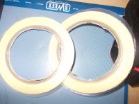
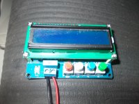
I have ordered this counter for measuring inductances and caps. unfortanely it did not work on induction, the LM311 oscillator does not oscillate, only elco,s I can measure and this are oke with precision.
I did need this to wind the resonant transformer, now I did already mail a week with that chinese supplyer without a solution.
I have measure the LM311 circuit, it is complete oke and has to oscillate, so, I think the LM is not really a LM311 but fakes or such who is soldered in by the company who make this meter.
So I think to build one myselfs with a PIC, I have all the stuff for it.
Maybe simeone here has also this experience? Why can china doe not make working stuff, ripping people off.
regards
Attachments
- Status
- This old topic is closed. If you want to reopen this topic, contact a moderator using the "Report Post" button.
- Home
- Design & Build
- Software Tools
- Calculation of SMPS resonant parts