The schematic in post below, reference and anode are shortcircuited, then the net is useless. C2, C9 caps and the resistor R13 are all shorted out.
Hi Osvaldo
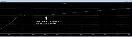
I have done the resonance in sim, but I have a strange problem, when I do set it on very low load, the feedback does run out to max voltages, en without a upgoing frequency, it looks like the output caps does this as it is a lowpass filter on almost dc.
Do you have a kind of idea about this?
thanks
Attachments
Most SMPS's need a minimum load to maintain the inductors running in the continuous current mode, except those specifically designed to run dry. Now, I know that resonant and quasi resonant need some small capacitances added to the tank to limit the maximum resonant frequency, where drivers and MOSFET's becomes more inefficient.
I think for audio, we need just to use open loop supply, feedback here does more harm then good, I can use lineair regulators for the tube filaments., just make the smps such that I have al voltages needed or maybe get used later.
For audio we need no feedback as people say here, but for me it was a learn fase to do implement it, but can easy be disconnected later.
I get good regulation when I have 5 amps minimum, I think also the vco from ltspice has a to low action on voltage, but maybe I do something wrong here.
regards
For audio we need no feedback as people say here, but for me it was a learn fase to do implement it, but can easy be disconnected later.
I get good regulation when I have 5 amps minimum, I think also the vco from ltspice has a to low action on voltage, but maybe I do something wrong here.
regards
I think for audio, we need just to use open loop supply, feedback here does more harm then good...
I don't imagine why, and without feedback, how will the SMPS maintain the output voltage(s)? Is very risky this.
I made a SMPS with UC3842, STP7N60, PC817 and TL431 for my audio class AB (TDA2006´s and TDA2003's) and performs quite well from about 2 decades ago. Including, it survived a "paint tsunami" when some years ago while painting my house, a large paint stream droped in the STP7N60's heatsink (Grounded). Some sparks, no more.
Yesterday night, returning home in "bondi" (Bus), I was thinking about this topic, and I was wondering if U take into account in the simulations, loses in the circuit, Eddy, hysteresis, copper, etc. This represent a fixed load for the SMPS itself, limiting the frequency coverage of the controller.
Yesterday night, returning home in "bondi" (Bus), I was thinking about this topic, and I was wondering if U take into account in the simulations, loses in the circuit, Eddy, hysteresis, copper, etc. This represent a fixed load for the SMPS itself, limiting the frequency coverage of the controller.
No I do not have done that, I go build one, I am busy with the pcb, no feedback, and us therefore a uc3843 in fixed frequency and dutycycle 50 procent.
Simulation is a just try, real live is what I need, but the resoances are in the microhenrys and nanofarads, this will not respond on a 10 nH pcb trace.
Then I go play, or not when electrocuted.
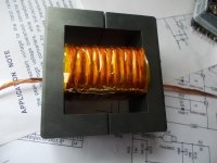
See this welder transformer, 4 Kw 160 amps.
regards
Attachments
For the problem with feedback loss at low load?.
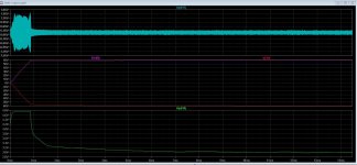
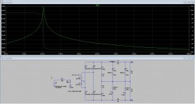
The solution seems that a LCC version resoant smps does a lot better there, signals looks
more stable, did just halve the capacitance of the resonant cap and did a extra one over the primairy coil, now the feedback does fine, I have ZCS and ZVS as result, even with no load.
Feedback does now the job,, with low and high load, does even the job now with just no load, open output. LCC does better, less ripple I did see also. These are quite good for welding smps
regards
Attachments
C2 = 470nF seems excessively high to me. I slows down too much the response of the filter and voltage sag with sudden loads will be. 1nF is quite better, in my experience.
It has to be 4.7n it do has inpact on speed, but it is also a pole, we need to do that right otherwise things get bad.
Q of tank is reason for feedback problems open output.
regards
Have a look at the primary overcurrent during power up while charging the secondary caps. Is it inside SOA of the PowerMOSFETs? I assume not so you will need some kind of softstart or current limit otherwise there is some good chance for the MOSFETs to blow upon the first power up.
Have a look at the primary overcurrent during power up while charging the secondary caps. Is it inside SOA of the PowerMOSFETs? I assume not so you will need some kind of softstart or current limit otherwise there is some good chance for the MOSFETs to blow upon the first power up.
Startup is high, but that will be done properly when build, the model has no soft startup, it is just a simple vco model.
Problem was the feedback, it runs out without load giving max unregulated voltage, a LCC version was able to do it properly, so I think the tank gain or Q is cause.
The softstart is included in the chip, I believe it starts below resonance or above, (what is used) and adjust after caps are charged.
I need a proper calculation program for multiply outputs, I see it affects resoance when used not properly.
regards
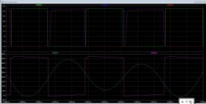
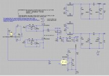
Here I have the simulation for the tube supply in resonabce, it is open loop and I did see that it keeps quite good the voltages when amps get drawn, on max, just 2 volts.
I go use LM type of regulators after the 18 volts out, for the tubes filament.
I am a little worried beacuse of the calculation of the multiply windings for all the voltages, it afeect resonance and it is not easy to calculate, so need of doe it experimentally or I can use a resonance forward calculator to get close, there is calcular who can do more supply voltages.
regards
Attachments
I did not can resist to solve the feedback version for th tubes, I have managed to learn some more, Now i do now also how to do it.
The magnetics and the windings are a uge factor also the Qr and Lr Lm , in fact it is not that hard, for open loop keep the resonance above max gain, say some 10 khz, and it do well.
For the feedback and the low load, just adjust the secondary such that the feedback falls into the gain area.
But making a transformer with more outputs in real live? I have to see what happens.
I go start now with the design, first the small one, then de bigger one, I skin them alive.
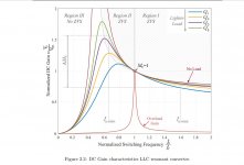
Here nice reading about the resonnat converters.
https://pdfs.semanticscholar.org/ffeb/3724fb28d92dedb760940929534e0e62960d.pdf
regards
The magnetics and the windings are a uge factor also the Qr and Lr Lm , in fact it is not that hard, for open loop keep the resonance above max gain, say some 10 khz, and it do well.
For the feedback and the low load, just adjust the secondary such that the feedback falls into the gain area.
But making a transformer with more outputs in real live? I have to see what happens.
I go start now with the design, first the small one, then de bigger one, I skin them alive.
Here nice reading about the resonnat converters.
https://pdfs.semanticscholar.org/ffeb/3724fb28d92dedb760940929534e0e62960d.pdf
regards
Attachments
Why the +15V output is half wave rectified, while the other are full wave?
Shottky diodes in the 320V arm? Mmmm, rare.
I had that with the high voltages of 320 volts half wave did not so good, get lower voltage and need induction up, saw
also with high voltages these are full wave. the 15 volts is for tube filament so not so much a problem i think. I can
use two transformer coils as i see much with two diodes.
But I can always change when building it to see whap happens, alsow ith rectifier stresses.
I have not seen the skottky, but change them for fast recovery types.
regards
regards
Last edited:
But the single phase rectifier do affects the loading of the traffo, creating flux imbalance.
It continues making me noise the idea of working the device at open loop.
So you advise to use double winding wit two diodes or a single winding with full bridge rectifier?
For the feedback I have now all the needed info, the chip has burstmode for this kind of low load, or skipmode. Nut I have also did with sim, and saw that then I need a very wide frequency swing. I can regulate open output, bet then with full load it does not regulate and vica versa, Q of resonant system and Lm/Lr difference does also made much of impact on it.
Best then is just a open loop, just above resonance, or so high above resonance that shortcircuit is self protecting.
I have order some more parts like a newer resonance controller, L6599AD chip
regards
This is a better way?
I do see a 4 diode full bridge for the 320 volts does better then the two coil 2 diode version. for the low 15 volts 15 amps max one the two coil does oke, winding get more complicated because the two coils need precise winded, so maybe a 4 diode one coil is the best way.
I think the most difficult is wiinding the transformer, because how i calculate the different voltages properly, the Q of resonat and frequency does shift also, need to find a good
calculator, or a way to do it myself.
regards
Attachments
Last edited:
- Status
- This old topic is closed. If you want to reopen this topic, contact a moderator using the "Report Post" button.
- Home
- Design & Build
- Software Tools
- Calculation of SMPS resonant parts