I never saw a IGBT in such a resonant converters, because still those called "fast" are too low for usual PWM frequencies, may be I wrong. But in any case, a couple of MOSFET's are almost always used there, and the cost isn't too higher than IGBT's.
Some things I don't understand on the simulation. The 10MΩ ? Why? The 10nf cap to ground and it associated resistor? I humbly believe that you can simplify notoriously the schema. Keep in mind the poles/zeros schema needed in your circuitry, to place a feedback cutoff frequency near 1/5 of the lowest expected switching frequency, or the noise from the PWM section will be amplified and the entire PSU will oscillate with unpredictable results.
Some things I don't understand on the simulation. The 10MΩ ? Why? The 10nf cap to ground and it associated resistor? I humbly believe that you can simplify notoriously the schema. Keep in mind the poles/zeros schema needed in your circuitry, to place a feedback cutoff frequency near 1/5 of the lowest expected switching frequency, or the noise from the PWM section will be amplified and the entire PSU will oscillate with unpredictable results.
I never saw a IGBT in such a resonant converters, because still those called "fast" are too low for usual PWM frequencies, may be I wrong. But in any case, a couple of MOSFET's are almost always used there, and the cost isn't too higher than IGBT's.
Some things I don't understand on the simulation. The 10MΩ ? Why? The 10nf cap to ground and it associated resistor? I humbly believe that you can simplify notoriously the schema. Keep in mind the poles/zeros schema needed in your circuitry, to place a feedback cutoff frequency near 1/5 of the lowest expected switching frequency, or the noise from the PWM section will be amplified and the entire PSU will oscillate with unpredictable results.
I have used esim, do you now this site with calculator for all smps types.
PowerEsim - Free SMPS Switching Power Supply / Transformer Design Software
This did put there the Mohm resistors. I think because of poles and the use of the Lt431 as a integrator or such, as this is possible.
I am very bad with calculations, always was.
regards
I have built several LLC converters in the 400watt ballpark based on NCP1396 working without regulation. The fixed frequency is tuned to the series resonant tank. This gives best effeciency at full load and can be considered the switching equivalent to toroidal mains transformer supplies.
OK, I must recognize that resonant converter I didn't ever build one, but I repaired them. My preferred topology at low voltages is the current fed push-pull and in high ones, the flyback and the half bridge.
Several years ago I built a SEPIC + Cuk converter with tubes. No SS, only tubes. Pretty job.
Several years ago I built a SEPIC + Cuk converter with tubes. No SS, only tubes. Pretty job.
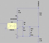
It seems to me that, R9 may or may not be as a function of the current split desired between diode (led) and this resistor to satisfice the regulator current. But, R31, R19, R20, C9 & C12 are unnecessary.
I have remove this parts and use the version who is used most, the extra poles from R13 and C9 in resonant versions.
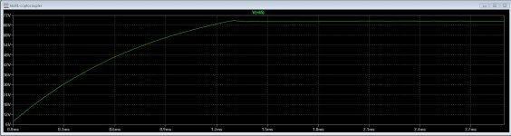
This does work but why does when I change R10 the voltage does not change? maybe bacause of the zener? because these does give other voltages when changt that zener who is normal afcouse after get over zenervoltage the optodiode get conduct and regulate then.
There are different systems out there with opto,s, need good formula,s and calculate because I think this is not such a complicated task.
regards
Attachments
I have built several LLC converters in the 400watt ballpark based on NCP1396 working without regulation. The fixed frequency is tuned to the series resonant tank. This gives best effeciency at full load and can be considered the switching equivalent to toroidal mains transformer supplies.
Yes I do now, and these stay quite stable, but now I do this to learn and I go try that and go also use it for the amp I have.
the smps for the 15, 300, and 120 x 120 volts is apart of this and is regulated, but I can also make that unregulated and use lineair voltage regulator for the tube filament voltages and even the high voltages so I get a big supply ripple supression.
regards
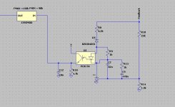
The schematic in post below, reference and anode are shortcircuited, then the net is useless. C2, C9 caps and the resistor R13 are all shorted out.
Hmmm yehh I have not see that error, no wonder R10 did nothing, but here is the working one, I have now made the setup.
For learning, I need to build a regulated type, can always be simple made unreguled after with some resistors.
I do use for ZVS above resonance regulation.
A question, I have a double coiled transformer from a old flat tv, as I have just need 69 uH I get there quickly with a normal transformer so we need a gapped one here?
regards
Attachments
As it is half bridge, and there is a cap blocking the DC in the trafo's primary, no need for gap except for the need of adjustment of the resonant frequencies, I believe that you may complete the resonant tank with some extra cap's over those parasitic ones, this fixes the maximum (?) frequency. Not sure now.
Be sure to take into account reflected capacitances and inductances, if in the secondary are there choke or capacitance input to the filter.
Be sure to take into account reflected capacitances and inductances, if in the secondary are there choke or capacitance input to the filter.
As it is half bridge, and there is a cap blocking the DC in the trafo's primary, no need for gap except for the need of adjustment of the resonant frequencies, I believe that you may complete the resonant tank with some extra cap's over those parasitic ones, this fixes the maximum (?) frequency. Not sure now.
Be sure to take into account reflected capacitances and inductances, if in the secondary are there choke or capacitance input to the filter.
Did feedback before the chokes, these are for ripple supression only, the question was because of the low induction needed some core do cause to little windings, and make that complicated.
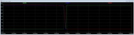
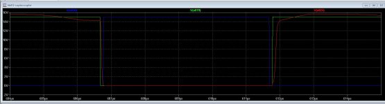
In simulation, the ZVS is present see the deadtime and gate switch on in that time.
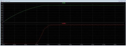
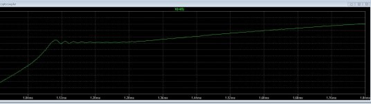
What I discover now in simulation, when output is open, only a 1 k resistor, the regulation do not work causing the smps to get full voltage, maybe cause is the output caps and time.
Attachments
Last edited:
OK, but can you post a schematic of the power sector of the PSU, so I can understand better what are trying to do? I'm getting a bit confused.
Attachments
Interesting. I have lack of some components, but still understandable. Why not to replace driver trafo for a SS driver (IR211x), I'm in doubt about coupled resonances through Miller capacitances from output trafo to driver trafo.
I like safety when thing blow the irs is also with the rest, a small transformer do well, special when new to it.
I do see the feedback get out of track when do output on high resistor like 1 k.
it do for a small moment lock, then loose.
resonant smps, are quite nice, there is a lot of them on the internet, so as soft switching and low emissions of emi, sinusoidal to the rectifier.
regards
Attachments
You may over-estimate the security of a gate transformer. Isolation often is tested with DC voltages - and with the high dV/dt rates applied from the bridge output I succeeded in burning them.
Gate transformers work best with constant duty cycle of 50%. Otherwise ugly things happen requiring complex circuitry for compensation.
And do consider the primary to secondary coupling capacitance in the ballpark of 100pF.
Last but not least they are pricey.
If you want a secure solution protecting the drivers when the power MOSFETs burn, I would go a different path:
Use your halfbridge driver and insert coupling caps into the gate lines. 10nF/300V-X2 or similar will do. In case of breakdown, the supply voltage is blocked and there will be a short charging pulse - which does not harm the driver.
And to enable DC coupling to the gates, a simple resistor 100kOhm/1W parallel to the coupling caps restores DC bias.
The power transformer normally is fitted with a gap. But not to tune the resonant frequency - stray inductance is hardly affected by the gap - but to generate enough magnetizing current that ensures ZVS swing during dead time.
Last edited:
Agree. I actually prefer a driver IC: less problems, less space, less footprint. And in case of "Puff", an IC more or an IC less, doesn't do the difference.
Also needed is a diode to make a DC restorer.
Thanks for advice, but I can wind such a transformer, it is quite easy, but maybe I do both, just for learning it.
I have 20 ir2110 if these are not fake.
regards
- Status
- This old topic is closed. If you want to reopen this topic, contact a moderator using the "Report Post" button.
- Home
- Design & Build
- Software Tools
- Calculation of SMPS resonant parts