VDMOS ZVP3306 model
Hi RCruz,
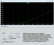
*VDMOS with subthreshold (c) Ian Hegglun
.model ZVP3306A VDMOS (pchan Rg=65 Vto=-3 Kp=80m
+ Rs=4 Ksubthres=0.15 Mtriode=0.5 Rd=3 Lambda=10m
+ Bex=-2.3 Vtotc=+6m tksubthres1=4m Trs1=3.5m Trd1=8m
+ Cgdmax=10p Cgdmin=5p a=0.5 Cgs=80p Cjo=25p
+ m=0.5 Vj=0.75 N=1.7 Is=5n Eg=1.2 Rb=0.15 Trb1=6m
+ Vds=-60 Ron=14 Qg=1.5nC mfg=DioIncIH1910)
Plot attached.
Cheers,
Hi RCruz,
*VDMOS with subthreshold (c) Ian Hegglun
.model ZVP3306A VDMOS (pchan Rg=65 Vto=-3 Kp=80m
+ Rs=4 Ksubthres=0.15 Mtriode=0.5 Rd=3 Lambda=10m
+ Bex=-2.3 Vtotc=+6m tksubthres1=4m Trs1=3.5m Trd1=8m
+ Cgdmax=10p Cgdmin=5p a=0.5 Cgs=80p Cjo=25p
+ m=0.5 Vj=0.75 N=1.7 Is=5n Eg=1.2 Rb=0.15 Trb1=6m
+ Vds=-60 Ron=14 Qg=1.5nC mfg=DioIncIH1910)
Plot attached.
Cheers,
Attachments
Thank you so muchHi RCruz,
*VDMOS with subthreshold (c) Ian Hegglun
.model ZVP3306A VDMOS (pchan Rg=65 Vto=-3 Kp=80m
+ Rs=4 Ksubthres=0.15 Mtriode=0.5 Rd=3 Lambda=10m
+ Bex=-2.3 Vtotc=+6m tksubthres1=4m Trs1=3.5m Trd1=8m
+ Cgdmax=10p Cgdmin=5p a=0.5 Cgs=80p Cjo=25p
+ m=0.5 Vj=0.75 N=1.7 Is=5n Eg=1.2 Rb=0.15 Trb1=6m
+ Vds=-60 Ron=14 Qg=1.5nC mfg=DioIncIH1910)
Plot attached.
Cheers,
Correcton for LND150 model Idss
Hi All,
My last LN150 model here has too high Idss for 'typical'. The corrected model code is below:
The range of Vto is Vto= -0.87 for Idss of 1mA and Vto= -1.63 for Idss of 3mA. For 'typical' as above Vto=-1.4.
My apologies for any inconvenience this may have caused. Thanks Keantoken for spotting it.
Hi All,
My last LN150 model here has too high Idss for 'typical'. The corrected model code is below:
Code:
 *VDMOS (c) Copyright Ian Hegglun Nov 2019
.model LND150 VDMOS (Rg=100 Vto=-1.4 Lambda=0m
+ Rs=70 Kp=3m Ksubthres=95m Mtriode=0.6 Rd=300
+ Bex=-2 Vtotc=-5m Tksubthres1=3m Trs1=2.6m Trd1=3m
+ Cgdmax=5p Cgdmin=3p a=0.3 Cgs=3p Cjo=15p m=0.7 VJ=0.75
+ IS=15p N=1.5 EG=1.1 Rb=100 Vds=400 Ron=600 mfg=IH1911)My apologies for any inconvenience this may have caused. Thanks Keantoken for spotting it.
")
I am really rusty at making spice models.
I would like to convert this subcircuit model to a standard ltspice model.
.model XXXX VDMOS(Rg= Rd=5 Rs=1 Vto= Kp= Cgdmax= Cgdmin= Cgs= Cjo= Is= Rb= )
Here is a first attempt please correct my dumb mistakes and add where there is missing data.
Cgdmax and min was taken from data sheet (attached) Cgd = Crss
Cgs was calculated using data sheet Cgs = Ciss - Crss (Cgd = Crss), ie 1600p -100p =1500p
The data taken from subcircuit model has been highlighted in bold
Here is my attempt below.
.model IRFP140 VDMOS(Rg= Rd= Rs= Vto=3.55 Kp=29.1392 Cgdmax=900p Cgdmin=100p Cgs=1500p Cjo= Is=1e-32 Rb= )
http://www.vishay.com/docs/91202/91202.pdf
.SUBCKT irfp140n 1 2 3
**************************************
* Model Generated by MODPEX *
*Copyright(c) Symmetry Design Systems*
* All Rights Reserved *
* UNPUBLISHED LICENSED SOFTWARE *
* Contains Proprietary Information *
* Which is The Property of *
* SYMMETRY OR ITS LICENSORS *
*Commercial Use or Resale Restricted *
* by Symmetry License Agreement *
**************************************
* Model generated on Apr 24, 96
* Model format: SPICE3
* Symmetry POWER MOS Model (Version 1.0)
* External Node Designations
* Node 1 -> Drain
* Node 2 -> Gate
* Node 3 -> Source
M1 9 7 8 8 MM L=100u W=100u
* Default values used in MM:
* The voltage-dependent capacitances are
* not included. Other default values are:
* RS=0 RD=0 LD=0 CBD=0 CBS=0 CGBO=0
.MODEL MM NMOS LEVEL=1 IS=1e-32
+VTO=3.55056 LAMBDA=0 KP=29.1392
+CGSO=1.23323e-05 CGDO=1.00023e-11
RS 8 3 0.0246012
D1 3 1 MD
.MODEL MD D IS=2.18703e-10 RS=0.00793395 N=1.23862 BV=100
+IBV=0.00025 EG=1.2 XTI=3.00435 TT=1e-07
+CJO=5.88419e-10 VJ=4.9869 M=0.76494 FC=0.5
RDS 3 1 4e+06
RD 9 1 0.00710688
RG 2 7 3.90167
D2 4 5 MD1
* Default values used in MD1:
* RS=0 EG=1.11 XTI=3.0 TT=0
* BV=infinite IBV=1mA
.MODEL MD1 D IS=1e-32 N=50
+CJO=1.70479e-09 VJ=0.5 M=0.58486 FC=1e-08
D3 0 5 MD2
* Default values used in MD2:
* EG=1.11 XTI=3.0 TT=0 CJO=0
* BV=infinite IBV=1mA
.MODEL MD2 D IS=1e-10 N=0.4 RS=3e-06
RL 5 10 1
FI2 7 9 VFI2 -1
VFI2 4 0 0
EV16 10 0 9 7 1
CAP 11 10 3.76147e-09
FI1 7 9 VFI1 -1
VFI1 11 6 0
RCAP 6 10 1
D4 0 6 MD3
* Default values used in MD3:
* EG=1.11 XTI=3.0 TT=0 CJO=0
* RS=0 BV=infinite IBV=1mA
.MODEL MD3 D IS=1e-10 N=0.4
.ENDS
Last edited:
Hi 2 picoDumbs,
An easy way is to use the IRFP150 VDMOS with an area scale factor m=0.5.
Place the MOSFET and enter "IRFP150 m=0.5"
Add the model code below:
*VDMOS with subthreshold (c) Ian Hegglun
.model IRFP150 VDMOS (Rg=2 Vto=4.0 Kp=22 Lambda=3m
+ Rs=30m Ksubthres=0.15 Mtriode=0.35 Rd=30m
+ Bex=-1.6 Vtotc=-6m Tksubthres1=4m Trs1=3.5m Trd1=5m
+ Cgdmax=4.6n Cgdmin=100p a=0.35 Cgs=3n Cjo=1n
+ m=0.4 VJ=0.75 IS=1n N=1.5 Eg=1.35 Rb=5m Trb1=3m
+ Vds=100 Ron=50m Qg=140nC mfg=VishIH1907)
-------
The area scale factor can be estimated from RDSon or Gfs or Ciss by comparing the two datasheets when they are the same voltage rating, same manufacturer and same process (generation).
If you want to convert to your own IRFP140 model then scale R values by 2 and C values by 0.5, and Kp by 0.5. Vto and temp-cos and the others stay the same.
My site has info on the VDMOS here VDMOS - PAK2 devo
I hope that helps.
All the best for the new year.
Hi 2 picoDumbs,
An easy way is to use the IRFP150 VDMOS with an area scale factor m=0.5.
Place the MOSFET and enter "IRFP150 m=0.5"
Add the model code below:
*VDMOS with subthreshold (c) Ian Hegglun
.model IRFP150 VDMOS (Rg=2 Vto=4.0 Kp=22 Lambda=3m
+ Rs=30m Ksubthres=0.15 Mtriode=0.35 Rd=30m
+ Bex=-1.6 Vtotc=-6m Tksubthres1=4m Trs1=3.5m Trd1=5m
+ Cgdmax=4.6n Cgdmin=100p a=0.35 Cgs=3n Cjo=1n
+ m=0.4 VJ=0.75 IS=1n N=1.5 Eg=1.35 Rb=5m Trb1=3m
+ Vds=100 Ron=50m Qg=140nC mfg=VishIH1907)
-------
The area scale factor can be estimated from RDSon or Gfs or Ciss by comparing the two datasheets when they are the same voltage rating, same manufacturer and same process (generation).
If you want to convert to your own IRFP140 model then scale R values by 2 and C values by 0.5, and Kp by 0.5. Vto and temp-cos and the others stay the same.
My site has info on the VDMOS here VDMOS - PAK2 devo
I hope that helps.
All the best for the new year.
Excellent guidance, Ian. Happy New Year.
Cheers,
Bob
Hi 2 picoDumbs,
An easy way is to use the IRFP150 VDMOS with an area scale factor m=0.5.
Place the MOSFET and enter "IRFP150 m=0.5"
Add the model code below:
*VDMOS with subthreshold (c) Ian Hegglun
.model IRFP150 VDMOS (Rg=2 Vto=4.0 Kp=22 Lambda=3m
+ Rs=30m Ksubthres=0.15 Mtriode=0.35 Rd=30m
+ Bex=-1.6 Vtotc=-6m Tksubthres1=4m Trs1=3.5m Trd1=5m
+ Cgdmax=4.6n Cgdmin=100p a=0.35 Cgs=3n Cjo=1n
+ m=0.4 VJ=0.75 IS=1n N=1.5 Eg=1.35 Rb=5m Trb1=3m
+ Vds=100 Ron=50m Qg=140nC mfg=VishIH1907)
-------
The area scale factor can be estimated from RDSon or Gfs or Ciss by comparing the two datasheets when they are the same voltage rating, same manufacturer and same process (generation).
If you want to convert to your own IRFP140 model then scale R values by 2 and C values by 0.5, and Kp by 0.5. Vto and temp-cos and the others stay the same.
My site has info on the VDMOS here VDMOS - PAK2 devo
I hope that helps.
All the best for the new year.
Awesome.
Thank you
The gentleman hanging around this thread are mighty helpful.
I am going to push my luck here for some general understanding on the various IRFP parts available from various manufactures.
This is my current understanding (which quite likely is inaccurate) :
Vishay purchased some of International Rectifiers business (possibly factories?)
Infineon purchased the remaining parts of International Rectifiers business.
Then you have companies like OnSemi, Ixys, StMicro, also making these parts either currently or in the past.
Looking at the specs of for example IRFP250 between companies there are differences eg Vishay vs Infineon
Vishay label their parts as "3rd Generation" and Infineon label their parts as "5th Generation" (see data sheets).
http://www.vishay.com/docs/91212/91212.pdf
https://www.infineon.com/dgdl/irfp250npbf.pdf?fileId=5546d462533600a4015356288b8b1fde
Is this just marketing bs, or if the manufacturing process has changed between Vishay's Third Gen, and Infineon's Fifth Gen, does anyone know what has changed, and are these changes of benefit for linear operation (both high biased Class AB and Class A operation)?
It appears (from datasheet specs) Rdson, Capacitances, and Power Rating are a little better in the Infineon devices, or is this just Infineon "doctoring" their testing methodologies?
I don't think I see differences in transcoductance (Id vs Vgs) on the datasheets between the two.
Then you have M parts and N parts by Infineon eg IRFP250MPbf and IRFP250NPbf with absolutely no clue as to what the differences are.
https://www.infineon.com/dgdl/irfp250mpbf.pdf?fileId=5546d462533600a4015356287bc71fda
https://www.infineon.com/dgdl/irfp250npbf.pdf?fileId=5546d462533600a4015356288b8b1fde
Then there is Ixys, OnSemi, StMicro, and probably other obsolete versions Harris, etc.
It's a bloody dog's breakfast when it comes to selecting parts.
I don't particularly want to buy all of them just to personally test them.
I am guessing someone here has compared them or know some of the answers to these questions.
Please enlighten me regarding Infineon vs Vishay (or any of the other manufactrers) before I have a melt down.
Thank you
Last edited:
Hi Bob Cordell
I am not sure if anyone has noticed this before, but I was just testing these models
* IRFP240C VDMOS copyright Cordell Audio December 6, 2010
.model irfp240C VDMOS(nchan Vto=4.0 Kp=4.8 Lambda=0.0032 Rs=0.01 Rd=0.1 Rds=1e7 Cgdmax=2600p Cgdmin=10p a=0.35 Cgs=1250p Cjo=3000p m=0.75 VJ=2.5 IS=4.0E-06 N=2.4)
*
* IRFP9240C VDMOS copyright Cordell Audio December 6, 2010
.model irfp9240C VDMOS(pchan Vto=-3.76 Kp=9 Lambda=0.004 Rs=0.064 Rd=0.1 Rds=1e7 Cgdmax=1200p Cgdmin=15p a=0.26 Cgs=1130p Cjo=2070p m=0.68 VJ=2.5 IS=4.0E-06 N=2.4)
Anyway, getting to crux of the matter, IRFP9240C is giving me higher transconductance than IRFP240C (measured at 1.5A) this seems opposite to what the Vishay data sheets suggests.
http://www.vishay.com/docs/91210/91210.pdf
https://www.vishay.com/docs/91239/sihfp924.pdf
Should I just switch the Kp values?
Last edited:
Actually Bob I need to triple check these measurements.
Measuring Id vs Vgs (using cursors) between Id =1A and Id at delta +1V Vgs gives similar curves (still closer than the data sheet suggests)
Results using Cursors
IRFP240C
(Vgs = 4.636V, Id = 1A), (Vgs = 5.636V, Id = 6.3A)
IRFP9240C
(Vgs = 4.278V, Id = 1A), (Vgs = 5.278V, Id = 6.1A)
For the same kind of measurement taken from data sheet (starting at Id= 1A), we get around 8A and 5.5A for 240, 9240 respectively.
http://www.vishay.com/docs/91210/91210.pdf
https://www.vishay.com/docs/91239/sihfp924.pdf
Taking the derivative of the curves seems to indicate something more different than the other method would suggest. I need to check this one.
Last edited:
Sometimes different datasheets for the same part disagree somewhat on curves, especially between manufacturers. It might not be a mistake, just a different manufacturer's datasheet was used, or possibly even measured data. Sometimes I try to collect all the different datasheets for the same part and then choose one with the most complete dataset if it will be representative of the currently available parts. But I by far prefer actual measured data.
But I by far prefer actual measured data.
Yeah. I agree.
Once I get home, I will start measuring the parts I have.
Hi UltimateX86,HI
... the temperature variation has no effect
thanks
The temp-cos were not set for Vtotc and BetaTc. Added now. See attached. Temp is stepped 25 and 125. Also gfs and Vto have been trimmed closer to the datasheet.
Cheers,
Attachments
Correct lateral models?
There is some discussion over in the First Watt F7 review thread about the proper parameters for laterals like the 10P20 and the 10N20. We are hoping Ian or keantoken can chime in. See for example:
First Watt F7 review
Thanks!
There is some discussion over in the First Watt F7 review thread about the proper parameters for laterals like the 10P20 and the 10N20. We are hoping Ian or keantoken can chime in. See for example:
First Watt F7 review
Thanks!
- Home
- Design & Build
- Software Tools
- Better power MOSFET models in LTSpice