Sorry, there was a mistake in the IRF640/9640 models. Here are the corrected models:
Code:
*VDMOS with subthreshold (c) Ian Hegglun Aug 2015
.model IRF640-25C VDMOS (Rg=5 Vto={4.30-6m*0} Lambda=3m
+ Rs={35m*(1+3.5m*0)} Kp={13.0/(1+8.8m*0)}
+ Ksubthres={0.23*(1+4m*0)} Mtriode={0.35} Rd={0.1*(1+5m*0)}
+ Cgdmax=2600p Cgdmin=10p a=0.35 Cgs=1250p Cjo=3000p
+ m=0.75 VJ=5 IS=1n N=1.3 Rb=0.01 )

*VDMOS with subthreshold (c) Ian Hegglun Aug 2015
.model IRF9640-25C VDMOS (pchan Rg=6 Vto={-3.76+2.5m*0} Lambda=4m
+ Rs={68m*(1+3m*0)} Kp={9.0/(1+3m*0)}
+ Ksubthres={0.2*(1+4m*0)} Mtriode={0.3} Rd={0.25*(1+9m*0)}
+ Cgdmax=1200p Cgdmin=15p a=0.26 Cgs=1130p Cjo=2070p
+ m=0.75 VJ=2.5 IS=1p N=1.5 Rb=0.02 )

*VDMOS with subthreshold (c) Ian Hegglun Aug 2015
.model IRF640-75C VDMOS (Rg=5 Vto={4.30-6m*50} Lambda=3m
+ Rs={35m*(1+3.5m*50)} Kp={13.0/(1+8.8m*50)}
+ Ksubthres={0.23*(1+4m*50)} Mtriode={0.35} Rd={0.1*(1+5m*50)}
+ Cgdmax=2600p Cgdmin=10p a=0.35 Cgs=1250p Cjo=3000p
+ m=0.75 VJ=5 IS=1n N=1.3 Rb=0.01 )

*VDMOS with subthreshold (c) Ian Hegglun Aug 2015
.model IRF9640-75C VDMOS (pchan Rg=6 Vto={-3.76+2.5m*50} Lambda=4m
+ Rs={68m*(1+3m*50)} Kp={9.0/(1+3m*50)}
+ Ksubthres={0.2*(1+4m*50)} Mtriode={0.3} Rd={0.25*(1+9m*50)}
+ Cgdmax=1200p Cgdmin=15p a=0.26 Cgs=1130p Cjo=2070p
+ m=0.75 VJ=2.5 IS=1p N=1.5 Rb=0.02 )

*VDMOS with subthreshold (c) Ian Hegglun Aug 2015
.model IRF640-Tjp VDMOS (Rg=5 Vto={4.30-6m*(Tjp-25)} Lambda=3m
+ Rs={35m*(1+3.5m*(Tjp-25))} Kp={13.0/(1+8.8m*(Tjp-25))}
+ Ksubthres={0.23*(1+4m*(Tjp-25))} Mtriode={0.35} Rd={0.1*(1+5m*(Tjp-25))}
+ Cgdmax=2600p Cgdmin=10p a=0.35 Cgs=1250p Cjo=3000p
+ m=0.75 VJ=5 IS=1n N=1.3 Rb=0.01 )

*VDMOS with subthreshold (c) Ian Hegglun Aug 2015
.model IRF9640-Tjp VDMOS (pchan Rg=6 Vto={-3.76+2.5m*(Tjp-25)} Lambda=4m
+ Rs={68m*(1+3m*(Tjp-25))} Kp={9.0/(1+3m*(Tjp-25))}
+ Ksubthres={0.2*(1+4m*(Tjp-25))} Mtriode={0.3} Rd={0.25*(1+9m*(Tjp-25))}
+ Cgdmax=1200p Cgdmin=15p a=0.26 Cgs=1130p Cjo=2070p
+ m=0.75 VJ=2.5 IS=1p N=1.5 Rb=0.02 )
Last edited:
Hi Kean,
I see you have shown models for 25°C and for 75°C
What is Tjp?
Temp is parameterized - you will see in the model 'Tjp' which you can then specify in the sim so you can sim at any temp or at stepped temp.
Jan
I mean, can I use exicon mosfet in simulation but use 2KS1058/SJ162 in real amplifier? I'm worry about biasing the mosfet. But I can accept if the result have higher distortion.
The Renesas Lateral MOSFETs are pretty easy to work with, and while not as robust as the IRFP240/9240 they are somewhat self-limiting when they over-heat. Note that the pinout for the 2SJ162/K1058 is GSD while the IRFP's are GDS.
Weaver's contribution to the vacuum tube spice modelling thread -- pentode portion -- for those who like to play around with equations.
Sorry, there was a mistake in the IRF640/9640 models. Here are the corrected models:
Dear keantoken,
are the models for original IR IRF640/9640 or are the models for Vishay types?
Could we use FQP19N20/FQP12P20 as replacement for IRF640/9640?
BR, Toni
They were based on the Vishay datasheets, but the graphs in those sheets are just redigitized versions of the graphs in the IR datasheets (common practice with many companies such as Fairchild, OnSemi, etc.). So I would consider them IR models.
I would think most audio amps could be adjusted to accept almost any MOSFETs, and I don't see any reason the FQP's would blow up. That's the most I can say since I've never tested those MOSFETs.
I would think most audio amps could be adjusted to accept almost any MOSFETs, and I don't see any reason the FQP's would blow up. That's the most I can say since I've never tested those MOSFETs.
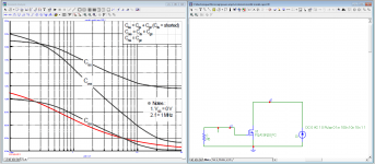
Someone asked about verifying the model capacitances. Some models have fixed capacitances, and they will give fake results. Fortunately, there is an easy way to check.
We start in transient mode, with Vds=0. Then, the constant current source charges the drain-source and drain-gate capacitances. Since C = I/(dV/dt), we can plot this capacitance easily and compare with the datasheet curves. This is the Fairchild model.
The capacitance we're measuring corresponds very well to the datasheet Crss. However, we're measuring Coss. The models seems wrong here.
Attachments
Last edited:
Yes, the curve is close, but it's the wrong curve ! Coss versus Crss.
I'm using Microcap, and the FQA19N20 model is a subckts : diodes are used to model capacitance. The FQP12P20 model is a BSIM3 one by Fairchild.
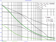
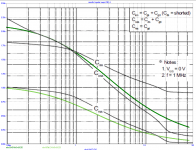
Now, for FQP12P20, the PMOS complimentary. Its datasheet capacitances are very similar to the FQP19N20, which is good.
Its model (green) is completely bollocks compared to the datasheet.
I was wondering why my MOSFET amp simulations showed a PMOS being much faster than the NMOS, which isn't supposed to happen. So, that was the reason ! The capacitances are wayyyyyy optimistic. Also, in the crossover region, the BSIM3 model does... nasty things.
I'm using Microcap, and the FQA19N20 model is a subckts : diodes are used to model capacitance. The FQP12P20 model is a BSIM3 one by Fairchild.
Now, for FQP12P20, the PMOS complimentary. Its datasheet capacitances are very similar to the FQP19N20, which is good.
Its model (green) is completely bollocks compared to the datasheet.
I was wondering why my MOSFET amp simulations showed a PMOS being much faster than the NMOS, which isn't supposed to happen. So, that was the reason ! The capacitances are wayyyyyy optimistic. Also, in the crossover region, the BSIM3 model does... nasty things.
Attachments
Last edited:
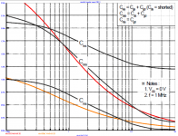
Crss is traced by measuring the current in the gate resistance. Coss is red, Coss orange. I tweaked the model to have a better match with the datasheet Coss/Crss. Unfortunately, I do not have a FQP19N20 sample to actually measure it for real, so please take the following model with a grain of salt.
Measurement would be simple, though :
- Connect D to any AC voltage
- Short G and S and connect to GND via resistor
- Use scope in XY+Math mode...
Code:
.SUBCKT  FQA19N20_FC2   20  10  30
Rg     10    1    1
M1      2    1    3    3    DMOS    L=1u   W=1u
.MODEL DMOS NMOS (VTO={4.53*{-0.00093*TEMP+1.02325}}  KP={14.5*{-0.00055*TEMP+1.01375}}
+ THETA=0.04  VMAX=1.1E5  LEVEL=3)
Cgs     1    3    1200p
Rd      20   4    12m      TC=0.01
Dds     3    4    DDS
.MODEL     DDS    D(BV={200*{0.0008*TEMP+0.98}} M=0.64  CJO=1900p  VJ=0.58)
Dbody   3    20   DBODY
.MODEL DBODY  D(IS=3.5E-13   N=1.0   RS=16.3m   EG=1.1  TT=140n)
Ra      4    2    43m     TC=0.01
Rs      3    5    2.3m
Ls      5    30   1.0n
M2      1    8    6    6   INTER
E2      8    6    4    1   2
.MODEL   INTER    NMOS(VTO=0   KP=10   LEVEL=1)
Cgdmax  7    4    1080p
Rcgd    7    4    10Meg
Dgd     6    4    DGD
Rdgd    4    6    10meg
.MODEL     DGD    D(M=0.58  CJO=1180p   VJ=0.38)
M3      7    9    1    1   INTER
E3      9    1    4    1   -2
.ENDS FQA19N20_FC
Measurement would be simple, though :
- Connect D to any AC voltage
- Short G and S and connect to GND via resistor
- Use scope in XY+Math mode...
Attachments
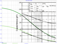
Now, about that PMOS. I got a IRFP9240 model from one of Bob Cordell's posts.
First picture is this IRFP9240 model, versus IRFP9240 datasheet. It matches perfectly. Second picture is the same model versus FQP12P20. It also matches very well. Therefore, IRFP9240 model can be used to investigate the frequency response of both FETs.
FQP12P20 has more transconductance, so it would be a better match for the NMOS, but it also has an impractical package (TO220).
Code:
.SUBCKT irfp9240_EKV 1 2 3
**************************************
*      Model Generated by MODPEX     *
*Copyright(c) Symmetry Design Systems*
*         All Rights Reserved        *
*    UNPUBLISHED LICENSED SOFTWARE   *
*   Contains Proprietary Information *
*      Which is The Property of      *
*     SYMMETRY OR ITS LICENSORS      *
*Commercial Use or Resale Restricted *
*   by Symmetry License Agreement    *
**************************************
* Model generated on Oct 30, 96
* MODEL FORMAT: SPICE3
* Symmetry POWER MOS Model (Version 1.0)
* External Node Designations
* Node 1 -> Drain
* Node 2 -> Gate
* Node 3 -> Source
M1 9 7 8 8 MM L=100u W=100u
* Default values used in MM:
* The voltage-dependent capacitances are
* not included. Other default values are:
*   RS=0 RD=0 LD=0 CBD=0 CBS=0 CGBO=0
.MODEL MM pmos (
+ level=44
+ vto=-3.85
+ gamma=5.0
+ phi=3.0
+ kp=11
+ lambda=90
+ )
RS 8 3 0.0676019
D1 1 3 MD
.MODEL MD D IS=1e-20 RS=0.15 N=1.5 BV=200
+IBV=10 EG=1.2 XTI=4 TT=6.64764e-20
+CJO=1.10194e-09 VJ=2.90954 M=0.567236 FC=0.5
RDS 3 1 2e+06
RD 9 1 0.308023
RG 2 7 6.305
D2 5 4 MD1
* Default values used in MD1:
*   RS=0 EG=1.11 XTI=3.0 TT=0
*   BV=infinite IBV=1mA
.MODEL MD1 D IS=1e-32 N=50
+CJO=1.03967e-09 VJ=1.62532 M=0.841524 FC=1e-08
D3 5 0 MD2
* Default values used in MD2:
*   EG=1.11 XTI=3.0 TT=0 CJO=0
*   BV=infinite IBV=1mA
.MODEL MD2 D IS=1e-10 N=0.4 RS=3e-06
RL 5 10 1
FI2 7 9 VFI2 -1
VFI2 4 0 0
EV16 10 0 9 7 1
CAP 11 10 1.7452e-09
FI1 7 9 VFI1 -1
VFI1 11 6 0
RCAP 6 10 1
D4 6 0 MD3
* Default values used in MD3:
*   EG=1.11 XTI=3.0 TT=0 CJO=0
*   RS=0 BV=infinite IBV=1mA
.MODEL MD3 D IS=1e-10 N=0.4
.ENDS
Attachments
Bob:
In your entry #43 of 3rd January 2015, 06:27 PM I see spellings for the subthreshold parameter of both "ksubthes" (in the quote of 'ihquam') and "ksubthres" (in your .model statement).
Could you or anyone else clarify what the correct parameter spelling is? I was unable to simply replace the .model line of the IRFP240C with this statement. "Unknown parameter" for either spelling in the error log of LTSPICE XVII. Perhaps I've not properly set some operating parameter?
Thanks in advance,
t
RE: Correct sub threshold param
Ahem... sorry for the previous post. Figured it out by reading some more.
Bob: you may be interested to know I made some IRFP240 measurements of my own and got Id results very close to the Ckst model at the lower end... until it gets to the "knee" around 1 amp. Contact me via PM and I'll be happy to forward the Id vs Vgs table.
Links to improved models:
[*]IRF640/IRF9640
Hi K.
I have been at work on LTSpice models for the IXYS heavy duty power FETs.
Finished except for the capacitance of the body diode that sets Cds.
I have some idea but would like more, on the derivation of M and Vj, and what is the impact of N?
Do you have any comments on this, or was it done by Ian or Bob?
Best wishes
David
- Home
- Design & Build
- Software Tools
- Better power MOSFET models in LTSpice