I am trying out a model for the 2SK182 etc.
>> And while my 2SJ28 is working (and refers to a standard p-fet, pjf.asy)
I cannot get the 2SK180_audiohobby nor 2SK182_Watanabe to work.
The internal LTspice JFET symbols are used with devices defined with the .MODEL statement. The device models you have for the 2SK180 and 2SK182 are subcircuits which are incompatible with the built-in LTspice NJF symbol. The solution is to create new symbols that expect a device defined as a subcircuit instead of a "model." The easiest way to do this is to open the symbol file with a text editor, change the "SYMATTR Prefix" to X, and save the symbol to a new file with an "x" prefix. I've done this for you; the new symbols are attached (xnjf.asy.txt and xpjf.asy.txt). The forum won't allow uploading files with the .asy extension so you will need to rename these to xnjf.asy and xpjf.asy before you can use them.
I've labeled the terminals in the symbol files so that I can tell from the schematic whether it is the built-in .model symbol or the .subckt symbol, but you can remove these labels if you want.
I hope this helps.
Attachments
Last edited:
")
I'm helping a member with an active crossover on another thread. I feel it would be helpful if we could create a source for AC analysis which specifically has a non-flat level vs frequency, and phase which may contain non-minimum phase components, so that the behaviour of a speaker could be added to that of the crossover, without having to reverse engineer a circuit to do the same.
I'm helping a member with an active crossover on another thread. I feel it would be helpful if we could create a source for AC analysis which specifically has a non-flat level vs frequency, and phase which may contain non-minimum phase components, so that the behaviour of a speaker could be added to that of the crossover, without having to reverse engineer a circuit to do the same.
This concept has been used to generate a source that is equalized with a reverse RIAA curve so that it gives a flat response when sent through a RIAA preamp.
This could be the basis of what you want. I don't have the ref ready but should not be hard to find.
Jan
I'm helping a member with an active crossover on another thread. I feel it would be helpful if we could create a source for AC analysis which specifically has a non-flat level vs frequency, and phase which may contain non-minimum phase components, so that the behaviour of a speaker could be added to that of the crossover, without having to reverse engineer a circuit to do the same.
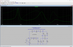
Sterophile Magazine developed a circuit that simulates a typical two-way sealed-box 8-ohm speaker. The circuit was published in the August 1995 issue. Here is a link to the article; see the second page for the revised circuit by John Atkinson.
Real-Life Measurements | Stereophile.com
Attached is the circuit drawn in LTspice. As shown, the simulated speaker is driven with a current source so that I could plot the impedance curve. But the node at the current source can be used as a signal voltage source that would vary according to the impedance curve. This might not be exactly what you want but maybe this will give you a few ideas.
Without the current source, the nodes 001 and ground represent the speaker terminals. I often use this "speaker" to test as a load with power amplifier designs. That's an approach to consider as well. Attached is the subcircuit SPICE model for the speaker, along with a symbol file to match. You will need to rename the symbol file to speaker.asy before you can use it.
Attachments
This concept has been used to generate a source that is equalized with a reverse RIAA curve so that it gives a flat response when sent through a RIAA preamp.
This could be the basis of what you want. I don't have the ref ready but should not be hard to find.
Jan
For anyone who is interested, here is an inverse RIAA model. The "n" parameter is used to "normalize" the amplitude output at 1 KHz to match the AC SIGNAL source. For example, if you want the PHONO output to be 1 mV at 1 KHz, set the AC signal to 1 mV.
Attachments
Last edited:
I am a newbie on Lt spice ,I DL Vacuum Tube SPICE Models
and put it in a folder "tube" in lib/sym.
But when I start the program and go in to component threres no tubes there...
And how do I Import this? JJ Tesla ECC99 spice model
and put it in a folder "tube" in lib/sym.
But when I start the program and go in to component threres no tubes there...
And how do I Import this? JJ Tesla ECC99 spice model
It's hard to know where to start...
First, you want the Ayumi_LTspice.zip file, which contains SPICE models for a number of tubes in a format compatible with LTspice. These will need to be extracted from the ZIP archive before they can be used. But you should place them under the "lib\sub" folder instead of the "lib\sym" folder. The "sym" folder is for symbols, and the "sub" folder is for subcircuits and library files.
The Ayumi models have to be used with a symbol file. Fortunately, LTspice has built-in tube symbols; these are in the symbol [Misc] folder. For "pentode" models you need to use the tetrode symbol rather than the pentode symbol, since most "pentode" models do not model the suppressor grid; that is, they are actually modeled as tetrodes.
The JJ Tesla ECC99 model that you linked is incompatible with LTspice. I've converted it to the format that LTspice expects and have attached it here.
Finally, you need to "include" the SPICE model in the schematic so that LTspice can find it. Attached is a simple schematic that illustrates the process. The include statement assumes that the model file ECC99_JJ.txt has been stored in the lib\sub\tube folder.
Good luck.
Attachments
Hmm I placed the schematic file and the txt file you attached in a folder sub/tube,and I can open the schema of Ecc99 but when I press run It says it cannot find the txt file.
And more basic how do I open the "build in" tubes When I look in Components tube it´s nothing there..
And more basic how do I open the "build in" tubes When I look in Components tube it´s nothing there..
Hmm I placed the schematic file and the txt file you attached in a folder sub/tube,and I can open the schema of Ecc99 but when I press run It says it cannot find the txt file.
Don't put your simulation (.asc) files in the sub or sym folders. Those folders should be used only for model and symbol files, respectively.
The schematic's include statement was based on you saying that you created a "tube" folder, which should be under the lib\sub folder rather than lib\sym as you did originally. If you use that directory structure, the .asc file will simulate properly because LTspice will interpret "tube\ECC99_JJ.txt" as "lib\sub\tube\ECC99_JJ.txt."
There are a lot of good tutorial posts in this thread. I think you would benefit by doing some study on your own. That's the best way to learn.
Quick question: how can I download model files from Github, like here:
LTSpice models for vacuum tubes * GitHub
... in a format that I can use in LTspice? Downloading the file gives me a .html file instead of a text file.
Jan
LTSpice models for vacuum tubes * GitHub
... in a format that I can use in LTspice? Downloading the file gives me a .html file instead of a text file.
Jan
- Home
- Design & Build
- Software Tools
- Installing and using LTspice IV (now including LTXVII), From beginner to advanced