Hi there all
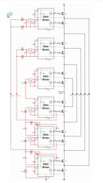
I try to simulate a flying cap stage, however do somebody now how to connect it to 4 switches and 2 drivers? and one flying capacitor want to use with symetric supply, in schematic it is done with single
supply, but for single I need symetrical afcourse, maybe somebody has tip or knowledge tot do it.
thanks
kees
Attachments
Hi
Maybe that is a good idea.
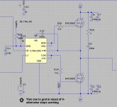
What is ltspice concerning is the mosfetdriver itselfs, normally there is a need of when using symerical supplys the supply of the driver ic needs connected there, however when I do that, model does not work anymore in LTspice, I do need to connect the negaive pin of the 5 volts to ground in stead of negative rail.
regards
Maybe that is a good idea.
What is ltspice concerning is the mosfetdriver itselfs, normally there is a need of when using symerical supplys the supply of the driver ic needs connected there, however when I do that, model does not work anymore in LTspice, I do need to connect the negaive pin of the 5 volts to ground in stead of negative rail.
regards
Attachments
 Oke grapje.
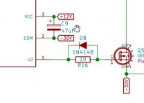
If you connect that voltage source bottom to -5V, your VDD 'supply' becomes 0V.
As noted, this is a circuit problem, nothing to do with LTspice.
Jan
Hi Jan
Not quite, it was the model itselfs who has a problem.
the model of the LMG5113 has no problem when tied the supply to the negatieve rail, what is needed for reference the mosfet source.
That is why the multilevel did not work, the model LMG1205 is as such not oke, connecting the supplt 5 volt to vss and negative rail do let it stop working, the supply 5 v was the problem, not vss, new model does fine..
I have however some strange behavior when simulating, defcon1 and a strange unstable continu run of the simulation time, but it does simulate and the signals looks oke.
regards
Attachments
Hi Jan
Not quite, it was the model itselfs who has a problem.
the model of the LMG5113 has no problem when tied the supply to the negatieve rail, what is needed for reference the mosfet source.
That is why the multilevel did not work, the model LMG1205 is as such not oke, connecting the supplt 5 volt to vss and negative rail do let it stop working, the supply 5 v was the problem, not vss, new model does fine..
I have however some strange behavior when simulating, defcon1 and a strange unstable continu run of the simulation time, but it does simulate and the signals looks oke.
regards
So did you get a new model? What did you change?
Jan
I have seen a schematic example where she are used floating. And the older 5113 does work fine and is exact the same chip as the 1205 only the last has a better bootstrap, the lmg5113 did need a resistor and diode extra because of it, and is changed in the 1205 where it is not needed anymore.
I go write this in the new tread.
Can I see somewhere if ground is connected in model? you now, this ltstuff I am not that good in.
What strange, I did not touch the mouse and still this post did get placed, weird.
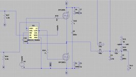
Here are the models, one does work lmg1205 not, but same parts, look at it just for fun.
regards
I go write this in the new tread.
Can I see somewhere if ground is connected in model? you now, this ltstuff I am not that good in.
What strange, I did not touch the mouse and still this post did get placed, weird.
Here are the models, one does work lmg1205 not, but same parts, look at it just for fun.
regards
Attachments
Last edited:
Your question is a circuit design problem, not an LTspice problem.
Although you might get an answer here, look for threads where the subject is amplifier stability or compensation.
Like the following, but there are more. Also, threads with 'Tian' or Middlebrook' in the title. Use the search function.
Jan
Although you might get an answer here, look for threads where the subject is amplifier stability or compensation.
Like the following, but there are more. Also, threads with 'Tian' or Middlebrook' in the title. Use the search function.
Jan
Attachments
Last edited:
I am trying out a model for the 2SK182 etc.
>> And while my 2SJ28 is working (and refers to a standard p-fet, pjf.asy)
I cannot get the 2SK180_audiohobby nor 2SK182_Watanabe to work.
In the thread on the 'hockey-puck' SIT's, I got the following advice from Ben Mah:
So here is how I (=Ben) did it:
I tried diligently (difficulties on the MAC aside). But this does not help. The error is: 'missing model definition for 2SK180. While it is on the page itself. However. the model says SUBCKT. Is the problem there?
The drop-down list for the model I created (that is njf.asy copied and renamed nsit.asy) is still that of an njf. For fun I added the SJEP120R100 to that list (by adding it to the standard database by Mike , STANDARD.jft) but that fortunately has a MODEL-text, not a SUBCKT-text.
The nSIT model @ {/library/application support/ltspice/lib/sym/nsit.asy} fails: whether I have put a name yet such as 2SK180 there or not, it complains of an "unknown subckt called" with some pin designations.
Please can someone help me out? I am restricted to the macos.
the working 2SJ28, on a pjf.asy:
>> And while my 2SJ28 is working (and refers to a standard p-fet, pjf.asy)
I cannot get the 2SK180_audiohobby nor 2SK182_Watanabe to work.
*2SK180
*GENERATED BY SIT MODELER @ AUDIOHOBBY.COM
*MODEL RANGE: 100V, 5A
*--------------------------------------------------
.SUBCKT 2SK180 D G S ; Drain Gate Source
+ PARAMS: MU=17 X=1.5 K=0.67 N=1.76 VCT=0 RG=2MEG
*--------------------------------------------------
B1 D S I=K*PWR(URAMP((V(G,S)+VCT)+(N*LN(V(D,S))+(V(D,S)/MU))),X)
R1 G S {RG}
CGS G S 2000P
CGD G D 2000P
CDS G S 0P
.ENDS 2SK180
*--------------------------------------------------
*--------------------------------------------------
*2SK182 version _Watanabe
*GENERATED BY SIT MODELER @ AUDIOHOBBY.COM
*MODEL RANGE: 30V, 4A
*--------------------------------------------------
.SUBCKT 2SK182 D G S ; Drain Gate Source
+ PARAMS: MU=22 X=1 K=0.9 N=0.63 VCT=1.18 RG=2MEG
*--------------------------------------------------
B1 D S I=K*PWR(URAMP((V(G,S)+VCT)+(N*LN(V(D,S))+(V(D,S)/MU))),X)
*FOR MULTISIM COMMENT OUT ABOVE LINE (*) AND UNCOMMENT NEXT LINE
*B1 D S I=K*PWR(MAX((V(G,S)+VCT)+(N*LN(V(D,S))+(V(D,S)/MU)),0),X)
R1 G S {RG}
CGS G S 2500P
CGD G D 5000P
CDS G S 500P
.ENDS 2SK182
*--------------------------------------------------
In the thread on the 'hockey-puck' SIT's, I got the following advice from Ben Mah:
So here is how I (=Ben) did it:
1. Find the njf.asy file in the LTSpice\lib\sym folder and double click to open it in LTSpice, then save it as nsit.asy
2. Right click on NJF. In my screen shot I had the p-channel open so I right clicked on PJF as this works for PJF to PSIT too
3. Change PJF (or NJF) to <Type>, then OK
4. Go to Edit Attributes and open
5. Change "Prefix" entry to X, "Value" entry to <Type>, "Description" entry to nSIT, then "OK"
6. nSIT can now be selected as a component
7. To enter component name, hover mouse arrow over component symbol until "hand with pointed finger" appears, then right click
The same can be done with pjf.asy to create psit.asy.
I tried diligently (difficulties on the MAC aside). But this does not help. The error is: 'missing model definition for 2SK180. While it is on the page itself. However. the model says SUBCKT. Is the problem there?
The drop-down list for the model I created (that is njf.asy copied and renamed nsit.asy) is still that of an njf. For fun I added the SJEP120R100 to that list (by adding it to the standard database by Mike , STANDARD.jft) but that fortunately has a MODEL-text, not a SUBCKT-text.
The nSIT model @ {/library/application support/ltspice/lib/sym/nsit.asy} fails: whether I have put a name yet such as 2SK180 there or not, it complains of an "unknown subckt called" with some pin designations.
Please can someone help me out? I am restricted to the macos.
the working 2SJ28, on a pjf.asy:
** 2SJ28 ************************************************** **********
*M. ROTHACHER
*--------------------------------------------------
.SUBCKT 2SJ28 1 2 3 ; Drain Gate Source
+ PARAMS: MU=4.9140 EX=2.352 KG1=101.25 KP=75.0 KVB=24.0 VCT=7.04 RGI=2MEG
*--------------------------------------------------
E1 7 0 VALUE={V(3,1)/KP*LN(1+EXP(KP*(1/MU+(VCT+V(3,2))/SQRT(KVB+V(3,1)*V(3,1)))))}
RE1 7 0 1G
G1 3 1 VALUE={(PWR(V(7),EX)+PWRS(V(7),EX))/KG1}
RDS 1 3 1G ; TO AVOID FLOATING NODES
D1 2 5 DX
R1 5 3 {RGI}
CGS 2 3 319P
CGD 1 2 142P
CDS 2 3 42P
.MODEL DX D(IS=1N RS=1 CJO=10PF TT=1N)
.ENDS
*--------------------------------------------------
Last edited:
4. Go to Edit Attributes and open
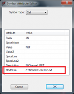
It looks like the asy file can't find the jfet model. Try editing the .asy file attributes, in the field "ModelFile" enter in the file path for the location of the 2sk182 jfet model, See attached example.
You can also drag and drop the jfet model into ltspice then with the mouse highlight the ".SUBCKT 2SJ28" then right click and create symbol.
Attachments
Last edited:
- Home
- Design & Build
- Software Tools
- Installing and using LTspice IV (now including LTXVII), From beginner to advanced