Ever have a need for a near perfect attenuator in LTSpice?
I wanted to cut down the output of an amp by 26dB so that the AC analysis and FFT plots would be referenced to 0dB. I originally used a resistive divider but I wanted something that wouldn't load the circuit so I came up with this.
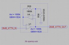
You add a couple of the 'opamp' components and the .lib statement to the schematic, wire it up as shown, then right click on each opamp and set the Aol and GBW values (those don't show on the schematic, I added them with the text tool). I don't think the Aol is critical, I just bumped them up an order of magnitude from the default, the GBW settings flatten the frequency response out into the exahertz region. Then you just have to play with the resistor values to get the attenuation you want.
Input impedance is basically infinite, output impedance is very close to zero, I measure it at around 50 nano ohms.
Hope this is useful to someone.
I wanted to cut down the output of an amp by 26dB so that the AC analysis and FFT plots would be referenced to 0dB. I originally used a resistive divider but I wanted something that wouldn't load the circuit so I came up with this.
You add a couple of the 'opamp' components and the .lib statement to the schematic, wire it up as shown, then right click on each opamp and set the Aol and GBW values (those don't show on the schematic, I added them with the text tool). I don't think the Aol is critical, I just bumped them up an order of magnitude from the default, the GBW settings flatten the frequency response out into the exahertz region. Then you just have to play with the resistor values to get the attenuation you want.
Input impedance is basically infinite, output impedance is very close to zero, I measure it at around 50 nano ohms.
Hope this is useful to someone.
Attachments
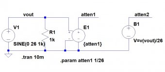

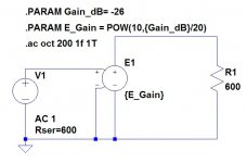
Okay, so I tried the voltage dependent voltage source method. You need a bit of math if you want to set the gain in decibels.
This appears to work for a general gain block, just change the Gain_dB param to whatever you want the gain in decibels to be, making it negative for attenuation.
This appears to work for a general gain block, just change the Gain_dB param to whatever you want the gain in decibels to be, making it negative for attenuation.
Attachments
Cute.Okay, so I tried the voltage dependent voltage source method. You need a bit of math if you want to set the gain in decibels.
This appears to work for a general gain block, just change the Gain_dB param to whatever you want the gain in decibels to be, making it negative for attenuation.
I am strugling with using the tetrode model.
Having connected an EF80 as triode (G2 to A), the grid outputs DC and the cathode nothing; input is also on output.
The model I found is the EF80 as tetrode, has only 4 pins ".SUBCKT EF80 1 2 3 4 ; P G K G2". But it does not work.

I used this EF80 model: and when I saw it did not work I just tested reversing pins and connection, that did,nt help.
thanks for some help! albert
**** EF80 ******************************************
* Created on 06/30/2017 03:10 using paint_kip.jar
* Model Paint Tools: Trace Tube Parameters over Plate Curves, Interactively
* Plate Curves image file: ef80.png
* Data source link: <plate curves URL>
*----------------------------------------------------------------------------------
.SUBCKT EF80 1 2 3 4 ; P G K G2
+ PARAMS: CCG=7.5P CGP=3.3P CCP=0.012P RGI=2000
+ MU=50 KG1=461.8 KP=261.8 KVB=22.2 KVC=1.57 VCT=0 EX=1.25 KG2=169.3
* Vp_MAX=350 Ip_MAX=50 Vg_step=1 Vg_start=0 Vg_count=8
* Rp=1600 Vg_ac=23.5 P_max=2.5 Vg_qui=-23.4 Vp_qui=240 UL=0.43 EG2=170
* X_MIN=69 Y_MIN=84 X_SIZE=953 Y_SIZE=683 FSZ_X=1942 FSZ_Y=1102 XYGrid=false
* showLoadLine=n showIp=y isDHP=n isPP=n isAsymPP=n isUL=n showDissipLimit=y
* showIg1=n gridLevel2=n isInputSnapped=n
* XYProjections=n harmonicPlot=y harmonics=y
*----------------------------------------------------------------------------------
RE1 7 0 1G ; DUMMY SO NODE 7 HAS 2 CONNECTIONS
E1 7 0 VALUE= ; E1 BREAKS UP LONG EQUATION FOR G1.
+{V(4,3)/KP*LOG(1+EXP((1/MU+(VCT+V(2,3))/V(4,3))*KP))}
G1 1 3 VALUE={(PWR(V(7),EX)+PWRS(V(7),EX))/KG1*ATAN(V(1,3)/KVB)}
* Alexander Gurskii screen current, see audioXpress 2/2011
RE2 8 3 1G ; Dummy
G2 8 3 VALUE={(PWR(V(7),EX)+PWRS(V(7),EX))/KG2*(KVC-ATAN(V(1,3)/KVB))}
E2 8 4 VALUE={0} ; Dummy
RCP 1 3 1G ; FOR CONVERGENCE
C1 2 3 {CCG} ; CATHODE-GRID 1
C2 1 2 {CGP} ; GRID 1-PLATE
C3 1 3 {CCP} ; CATHODE-PLATE
R1 2 5 {RGI} ; FOR GRID CURRENT
D3 5 3 DX ; FOR GRID CURRENT
.MODEL DX D(IS=1N RS=1 CJO=10PF TT=1N)
.ENDS
*$
Having connected an EF80 as triode (G2 to A), the grid outputs DC and the cathode nothing; input is also on output.
The model I found is the EF80 as tetrode, has only 4 pins ".SUBCKT EF80 1 2 3 4 ; P G K G2". But it does not work.
I used this EF80 model: and when I saw it did not work I just tested reversing pins and connection, that did,nt help.
thanks for some help! albert
**** EF80 ******************************************
* Created on 06/30/2017 03:10 using paint_kip.jar
* Model Paint Tools: Trace Tube Parameters over Plate Curves, Interactively
* Plate Curves image file: ef80.png
* Data source link: <plate curves URL>
*----------------------------------------------------------------------------------
.SUBCKT EF80 1 2 3 4 ; P G K G2
+ PARAMS: CCG=7.5P CGP=3.3P CCP=0.012P RGI=2000
+ MU=50 KG1=461.8 KP=261.8 KVB=22.2 KVC=1.57 VCT=0 EX=1.25 KG2=169.3
* Vp_MAX=350 Ip_MAX=50 Vg_step=1 Vg_start=0 Vg_count=8
* Rp=1600 Vg_ac=23.5 P_max=2.5 Vg_qui=-23.4 Vp_qui=240 UL=0.43 EG2=170
* X_MIN=69 Y_MIN=84 X_SIZE=953 Y_SIZE=683 FSZ_X=1942 FSZ_Y=1102 XYGrid=false
* showLoadLine=n showIp=y isDHP=n isPP=n isAsymPP=n isUL=n showDissipLimit=y
* showIg1=n gridLevel2=n isInputSnapped=n
* XYProjections=n harmonicPlot=y harmonics=y
*----------------------------------------------------------------------------------
RE1 7 0 1G ; DUMMY SO NODE 7 HAS 2 CONNECTIONS
E1 7 0 VALUE= ; E1 BREAKS UP LONG EQUATION FOR G1.
+{V(4,3)/KP*LOG(1+EXP((1/MU+(VCT+V(2,3))/V(4,3))*KP))}
G1 1 3 VALUE={(PWR(V(7),EX)+PWRS(V(7),EX))/KG1*ATAN(V(1,3)/KVB)}
* Alexander Gurskii screen current, see audioXpress 2/2011
RE2 8 3 1G ; Dummy
G2 8 3 VALUE={(PWR(V(7),EX)+PWRS(V(7),EX))/KG2*(KVC-ATAN(V(1,3)/KVB))}
E2 8 4 VALUE={0} ; Dummy
RCP 1 3 1G ; FOR CONVERGENCE
C1 2 3 {CCG} ; CATHODE-GRID 1
C2 1 2 {CGP} ; GRID 1-PLATE
C3 1 3 {CCP} ; CATHODE-PLATE
R1 2 5 {RGI} ; FOR GRID CURRENT
D3 5 3 DX ; FOR GRID CURRENT
.MODEL DX D(IS=1N RS=1 CJO=10PF TT=1N)
.ENDS
*$
Last edited:
I am strugling with using the tetrode model.
Having connected an EF80 as triode (G2 to A), the grid outputs DC and the cathode nothing; input is also on output.
The model I found is the EF80 as tetrode, has only 4 pins ".SUBCKT EF80 1 2 3 4 ; P G K G2". But it does not work.
View attachment 788118
I used this EF80 model: and when I saw it did not work I just tested reversing pins and connection, that did,nt help.
thanks for some help! albert
**** EF80 ******************************************
* Created on 06/30/2017 03:10 using paint_kip.jar
* Model Paint Tools: Trace Tube Parameters over Plate Curves, Interactively
* Plate Curves image file: ef80.png
* Data source link: <plate curves URL>
*----------------------------------------------------------------------------------
.SUBCKT EF80 1 2 3 4 ; P G K G2
+ PARAMS: CCG=7.5P CGP=3.3P CCP=0.012P RGI=2000
+ MU=50 KG1=461.8 KP=261.8 KVB=22.2 KVC=1.57 VCT=0 EX=1.25 KG2=169.3
* Vp_MAX=350 Ip_MAX=50 Vg_step=1 Vg_start=0 Vg_count=8
* Rp=1600 Vg_ac=23.5 P_max=2.5 Vg_qui=-23.4 Vp_qui=240 UL=0.43 EG2=170
* X_MIN=69 Y_MIN=84 X_SIZE=953 Y_SIZE=683 FSZ_X=1942 FSZ_Y=1102 XYGrid=false
* showLoadLine=n showIp=y isDHP=n isPP=n isAsymPP=n isUL=n showDissipLimit=y
* showIg1=n gridLevel2=n isInputSnapped=n
* XYProjections=n harmonicPlot=y harmonics=y
*----------------------------------------------------------------------------------
RE1 7 0 1G ; DUMMY SO NODE 7 HAS 2 CONNECTIONS
E1 7 0 VALUE= ; E1 BREAKS UP LONG EQUATION FOR G1.
+{V(4,3)/KP*LOG(1+EXP((1/MU+(VCT+V(2,3))/V(4,3))*KP))}
G1 1 3 VALUE={(PWR(V(7),EX)+PWRS(V(7),EX))/KG1*ATAN(V(1,3)/KVB)}
* Alexander Gurskii screen current, see audioXpress 2/2011
RE2 8 3 1G ; Dummy
G2 8 3 VALUE={(PWR(V(7),EX)+PWRS(V(7),EX))/KG2*(KVC-ATAN(V(1,3)/KVB))}
E2 8 4 VALUE={0} ; Dummy
RCP 1 3 1G ; FOR CONVERGENCE
C1 2 3 {CCG} ; CATHODE-GRID 1
C2 1 2 {CGP} ; GRID 1-PLATE
C3 1 3 {CCP} ; CATHODE-PLATE
R1 2 5 {RGI} ; FOR GRID CURRENT
D3 5 3 DX ; FOR GRID CURRENT
.MODEL DX D(IS=1N RS=1 CJO=10PF TT=1N)
.ENDS
*$
yes did append to me as well many times, just find some other EF80 spice model until you find the one matching the tetrode model of Ltspice.....all the best
try this one:
.SUBCKT EF80 1 2 3 4 ; A G2 G1 C;
* ExtractModel V .997
* Model created: 07-Dec-13
X1 1 2 3 4 PenthodeDE MU= 54.7 EX=1.202 kG1= 136.4 KP= 340.3 kVB = 4670.0 kG2= 584.2
+ Ookg1mOokG2=.56E-02 Aokg1=.23E-05 alkg1palskg2=.56E-02 be= .054 als= 3.09 RGI=2000
+ CCG1=7.5P CCG2=5.4P CPG1 = 0.007p CG1G2 = 2.6p CCP=0.012P ;
.ENDS
+1Is there any archive of the LTSpice Yahoo Group material?
All content gets wiped December 14th
Indeed, if such a resource exists, it would be a gross waste to loose whatever content / wisdom is in there. So the question re Archive of that thread - is very important.
Someone entered a schematic for me and I tried to load it in ver IV, it complained and gave me a blank screen, so
I loaded the latest version on another machine. One would think if it loads an old version that it would identify this and convert it to the new format and make a copy of the old version.
I noticed a few differences so far
1) Libraries, it references ones in a new folder in my documents path now. Okay I can accept that as hopefully it will not trash them in a update.
2) It does not remember the parameters for the .trans and .ac, why would they break something as simple as remembering these? or am I doing something wrong?
Last edited:
According to the developer it's not broken, but he never gave any explanation as to how it is better. He just says it should have been this way from the beginning.
So, it's free software, beggars can't be choosers.
Basically these days I just hold ctrl when editing any text on the schematic, and to change simulations I comment and uncomment the .trans/.ac/.noise or whatever lines.
So, it's free software, beggars can't be choosers.
Basically these days I just hold ctrl when editing any text on the schematic, and to change simulations I comment and uncomment the .trans/.ac/.noise or whatever lines.
How to check this tube circuit for stability
The attached asc. files are my attempt at a modification of a classic circuit and a check of stability. For the stability check I followed the directions in the linked video to the best of my ability and got the output seen in the attached PDF. Since the resulting plot looks nothing like what he got with the op amp circuit I’m wondering if I have messed things up.
Assuming I haven’t messed up the sim, I want to make sure I am not misinterpreting what I am seeing in the plot. To me it looks like the phase never swings more than 128 degrees from phase at mid band based on the dip in phase at 22kHz so the circuit should be stable. The thing that really screws me up here is that the gain line never crosses zero
About the asc files. The transformer model is based on what I have at hand, I have no idea how it relates to the original but it seems to work in this application. The original values are listed next to the parts I changed (U1 plate and cathode resistors and the feedback resistor) I did this to modify the gain and the operating point of U1 to make them more suitable for line stage use. The 12AY7 model I used is from my library and is included as a comment in the schematics. Sorry, I figured out how to add to the library first and have stuck with that rather than figuring out how to add models directly from the schematic.
Thanks for any help
Marty
Attachments
Errr ... Question please.
I want to use the Microchip model for the DN2540, which is an NMOS part. How do I bind that model to the LTspice NMOS symbol? Probably a no-brainer but don't know how to do it ...
Jan
*DN2540 MODEL
*
.MODEL DN2540 NMOS (LEVEL=3 RS=1.05 NSUB=5.0E14
+DELTA=0.1 KAPPA=0.20 TPG=1 CGDO=3.1716E-10
+RD=11 VTO=-1.50 VMAX=1.0E7 ETA=0.0223089
+NFS=6.6E10 TOX=725E-10 LD=1.698E-9 UO=862.425
+XJ=6.4666E-7 THETA=1.0E-5 CGSO=2.50E-9 L=4.0E-6
+W=59E-3)
.ENDS
*
Errr ... Question please.
I want to use the Microchip model for the DN2540, which is an NMOS part. How do I bind that model to the LTspice NMOS symbol? Probably a no-brainer but don't know how to do it ...
Jan
*DN2540 MODEL
*
.MODEL DN2540 NMOS (LEVEL=3 RS=1.05 NSUB=5.0E14
+DELTA=0.1 KAPPA=0.20 TPG=1 CGDO=3.1716E-10
+RD=11 VTO=-1.50 VMAX=1.0E7 ETA=0.0223089
+NFS=6.6E10 TOX=725E-10 LD=1.698E-9 UO=862.425
+XJ=6.4666E-7 THETA=1.0E-5 CGSO=2.50E-9 L=4.0E-6
+W=59E-3)
.ENDS
*
Hi Jan,
You could put this model as is in a spice directive directly in the schematic, then use it up by renaming the generic symbol to that model's name.
Works for diodes, bjts and whatever, so should work the same for those mos type of devices.
- Home
- Design & Build
- Software Tools
- Installing and using LTspice IV (now including LTXVII), From beginner to advanced