With difficulty I suspect. I've made models for things like the LM3886 chip amp as a basic discrete circuit and then turned it into a model. That is detailed in post #2272
https://www.diyaudio.com/community/...nner-to-advanced.260627/page-114#post-6320675
This might be easier if it does what you are after, use the LT3012 and 3015 models.

https://www.diyaudio.com/community/...nner-to-advanced.260627/page-114#post-6320675
This might be easier if it does what you are after, use the LT3012 and 3015 models.
Attachments
")
TI has a LM337 model which you can "auto generate" a symbol for.
https://www.ti.com/product/LM337?ke...rch-everything&usecase=GPN#design-development
https://www.ti.com/product/LM337?ke...rch-everything&usecase=GPN#design-development
I tried to install the new version (17) on Devuan GNU Linux and FAILED. The error is reported to be a configuration error. The earlier versions installed without issues.
If anyone succeeded to install it under Linux, please post. It seems the new version expects to find directories which were not needed in earlier versions.
What are these directories and how can they be created manually? If I remember well, they start with %username%. What is the real name of this placeholder?
Did you install wine-mono and wine-gecko from your repository (if it is available in your linux system. Mine is pclinuxos)?
Code:
apt-cache policy wine-mono
N: Unable to locate package wine-mono

apt-cache policy wine-gecko
N: Unable to locate package wine-geckoThe older versions used "C:\Users\username\Documents\LTspiceXVII"What are these directories and how can they be created manually? If I remember well, they start with %username%. What is the real name of this placeholder?
The latest version now uses this path - "C:\Users\username\AppData\Local\LTspice"
See the first post of this thread - https://www.diyaudio.com/community/threads/installing-the-new-2023-version-of-ltspice.394676/
The other versions installed while I was an unprivileged user. Since, this is an MS Windows program, I have to run it under WINE, which means many windows-like libraries will be active. As Windows is much like Swiss Cheese where security is involved, I will NOT install it as root. Under Devuan GNU Linux there is no need of running an antivirus. Installing as root would make the running of an anti-virus or better an anti-scumware, a requirement.
Last edited:
I have a phase problem in the current LTSpice XVII release that was not there in the past.
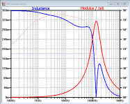
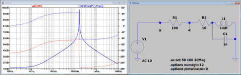
See attached diagram, a sim for a complex impedance.
Steering it the way a VNA does with a serial resistor an taking the signals from point A and R, one can get all the information, like value of inductance, capacity, resistance and impedance.
Here it is where things are going wrong.
For impedance the command "Mag" can be used, which in fact in Sqrt(Re^2+Im^2).
What "Mag" produces in the current LTSpice version is a correct impedance, but the phase is zero.
When doing the SQRT version, outcome is the same, still with zero phase, exactly on top of the Mag lines.
An older image is also attached from a different circuit, with the phase visible in dotted red, just as it should be.
When repeating the sim today for this model, the phase becomes zero, but the magnitude or modulus is correct.
Hans
Attachments

Re(), Im(), Mag() and Ph() return real values by definition, according to the help (for Version IV, as I don't use the broken newer versions). LTspice stores them as complex values with phase set to zero in order to keep the data format the same (no actual domain change).
"The functions Re(x) and Im(x) are available for complex data and
return a complex number with the real part equal to the real or imaginary part
of the argument respectively and the imaginary part equal to zero. The functions
Ph(x) and Mag(x) are also available for complex data and return a complex number
with the real part equal to the phase angle or magnitude of the argument
respectively and the imaginary part equal to zero."
Deriving full impedance -- with magnitude and phase -- with a mag() function seem wrong to me anyway as impedance is complex but mag() never is.
I'd simply use V(a)/I(R1)
KSTR, Thx for taking the time to answer my question.
And yes, you are right that taking V(a)/I(R1) should give the right answer.
By the way, V(a)/I(R1) is mathematically exactly the same as the used R1*V(a)/(V(r)-V(a))=R1*V(a)/(I(R1)*R1)=V(a)/I(R1)
So in future I will simply leave the "Mag" in front of it, an operator that always gave the correct phase in the past.
Who needs the magnitude of a complex impedance without a phase, and also sqrt(Re^2+Im^2) should have given the phase, but it didn't either., so I don't see any use of this "Mag" operator any more.
One last thing about this topic.
I simulated in the attachment both V(a)/I(R1) and R1*V(a)/(V(r)-V(a)), who as shown above are identical.
The modulus of the complex impedance in both cases is the same, but phase should start at zero degrees, which is not the case for V(a)/I(R1) ??
But this case can be closed.
Hans
Attachments
Hi All.
I have a question about smps transformer simulation in a LCC smps type converter.
Because a LCC is a current source output the transformer is designed like ;
The values of the leakage inductance Ls, the magnetizing inductance Lh and the transformer turns ratio n are based on the cantilever-model of a two winding transformer.
I did use the normal halfbridge calculation with excellentIT but can even use a full bridge to get higher inductance, the current source of the LCC needs high inductance as the cantilever model ordered. (if I am right.
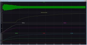
After calculate the inductances I do not get the proper voltages, even not with a normal half bridge, the high voltage 350 volts do not go further then 240 volts and the 120 volts go not further as 90 volts, the low voltages of 15 volts however go much higher, so when I lower that inductance, the high voltages do rize and the low voltage do drop as needed.
What is going on here?, for LCC i have a lot of papers who cover the resonance stuff, but not the transformer as she say it needs high impedance for LCC so it is less visible load as possible in design, I now the resonance voltage does go high and is a current source, who need a higher impedance.
I do calculate the inductances in exellentIT and do calculate the inductance per winding primairy (ExcellentIT do not give secondairy inductances on;y windings) so I do winding x calculated single winding inductance, possible this is not right as proportional stuff is needed?.
For LLC I have no problems designed whatsoever, much stuff for it, but I need high voltages so LCC is the best bet.
For sim part I think here are the guys I need for help.
regards.
I have a question about smps transformer simulation in a LCC smps type converter.
Because a LCC is a current source output the transformer is designed like ;
The values of the leakage inductance Ls, the magnetizing inductance Lh and the transformer turns ratio n are based on the cantilever-model of a two winding transformer.
I did use the normal halfbridge calculation with excellentIT but can even use a full bridge to get higher inductance, the current source of the LCC needs high inductance as the cantilever model ordered. (if I am right.
After calculate the inductances I do not get the proper voltages, even not with a normal half bridge, the high voltage 350 volts do not go further then 240 volts and the 120 volts go not further as 90 volts, the low voltages of 15 volts however go much higher, so when I lower that inductance, the high voltages do rize and the low voltage do drop as needed.
What is going on here?, for LCC i have a lot of papers who cover the resonance stuff, but not the transformer as she say it needs high impedance for LCC so it is less visible load as possible in design, I now the resonance voltage does go high and is a current source, who need a higher impedance.
I do calculate the inductances in exellentIT and do calculate the inductance per winding primairy (ExcellentIT do not give secondairy inductances on;y windings) so I do winding x calculated single winding inductance, possible this is not right as proportional stuff is needed?.
For LLC I have no problems designed whatsoever, much stuff for it, but I need high voltages so LCC is the best bet.
For sim part I think here are the guys I need for help.
regards.
Attachments
Hi Kees52. You mentioned that there is plenty of stuff for LLC half-bridge. By “stuff” do you mean LTSpice models?
If you do could you point me to some please? I’ve done some searching and while there’s plenty of theory and application notes I haven‘t been able to find any models.
If you do could you point me to some please? I’ve done some searching and while there’s plenty of theory and application notes I haven‘t been able to find any models.
I have drawn mine own schematic and use the vco in LTspice.
I can send some stuffff;-).
Problem is still, how to make the transformer for LCC, For LLC I have plenty idea,s and papers, LCC not..
And mine question here why LT spice give wrong voltages, special the high 350 volts when calculate with ExcellenIT.
Here it is.
I can send some stuffff;-).
Problem is still, how to make the transformer for LCC, For LLC I have plenty idea,s and papers, LCC not..
And mine question here why LT spice give wrong voltages, special the high 350 volts when calculate with ExcellenIT.
Here it is.
Attachments
- Home
- Design & Build
- Software Tools
- Installing and using LTspice IV (now including LTXVII), From beginner to advanced