...it looks like they work with whatever sim function is selected rather than different actual functions.
Yes, so it seems to be. My current workaround is to save a copy of the current model, open it and run the second type of simulation from there. Then it is a matter of arranging windows.
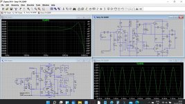
And since I have been doing these simulations only for a relatively short time then I just swapped the Y-axis scale to volts to see actually what was presented.
Thanks for the advice anyway.
My advice is free and worth every penny.

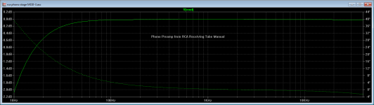
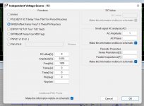
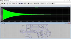
I usually adjust the AC signal level as Mooly shows in post # 2975 to set the output level to 1 volt (0 dB) at 1 KHz and display the results in decibels. Then when simulating a phono preamp, for example, I can see at a glance what the RIAA equalization error is across the audio band. Attached is an example for a phono preamp circuit shown in the RCA Receiving Tube Manual, modified slightly from the original.
FYI, I used the Ayumi model for the 12AX7 tube. A different model will give a different result, of course.
Attachments
Hi all
I get the flying cap multilevel not to work, I did had succes with optocouplers, but only when use a ground reference, I thought Jan.Didden mention this and I did try and works, the three level did not work because the fase shift of drive signal was in fase after the opto-coupler who is not the cause of the optocoupler itselfs, remove the bipolair supply and use a single voltage did work.
I think LTspice can not work well with this kind of circuits? plecs or powersim is better? I did try but these are complicated simulators.
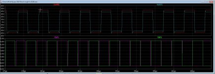
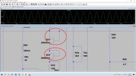
Oke maybe someone here has a idea why because also LTspice is not that simple, flying cap is referenced to ground making 5 level in bridge who is mine idea for a class d, I have much example papers reading but non simulate well, the cascaded multilevel however does fine. Inpicture you see signals from ltspice, below are fase shifted but in output it is fase again failing to make multileved signal afcourse. I can just build a test one in real, but did just sim for tp see what happens, maybe the flying cap needs to be charged for making sim working, to put a charge in it with IC statement..
did make a small video of what ltspice does, settings does not work maybe models who is not made for LTspice but does work and much people use them is possible cause, these are for Tina Pspice or other sim program.
Here is the sim file and the small movie to see, it does work and then stops.
Thanks in advance
regards
I get the flying cap multilevel not to work, I did had succes with optocouplers, but only when use a ground reference, I thought Jan.Didden mention this and I did try and works, the three level did not work because the fase shift of drive signal was in fase after the opto-coupler who is not the cause of the optocoupler itselfs, remove the bipolair supply and use a single voltage did work.
I think LTspice can not work well with this kind of circuits? plecs or powersim is better? I did try but these are complicated simulators.
Oke maybe someone here has a idea why because also LTspice is not that simple, flying cap is referenced to ground making 5 level in bridge who is mine idea for a class d, I have much example papers reading but non simulate well, the cascaded multilevel however does fine. Inpicture you see signals from ltspice, below are fase shifted but in output it is fase again failing to make multileved signal afcourse. I can just build a test one in real, but did just sim for tp see what happens, maybe the flying cap needs to be charged for making sim working, to put a charge in it with IC statement..
did make a small video of what ltspice does, settings does not work maybe models who is not made for LTspice but does work and much people use them is possible cause, these are for Tina Pspice or other sim program.
Here is the sim file and the small movie to see, it does work and then stops.
Thanks in advance
regards
Attachments
Maybe this helps, earlier I showed how to create a 'simulated' resistor
see Installing and using LTspice IV (now including LTXVII). From beginner to advanced.
Resistors can be used ad switches
1uOhm = On
1GOhm = Off
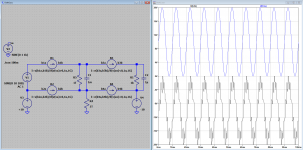
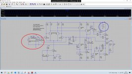
So I botched this together
There is an oscillator V2 generating v(va) that is used as the control voltage for the switches.
There is a voltage V1 to be 'transported' by the floating capacitor C1
Just run it and see how it functions.
P.s. I could not run/test the uploaded file due to the fact that I did not have the needed models
see Installing and using LTspice IV (now including LTXVII). From beginner to advanced.
Resistors can be used ad switches
1uOhm = On
1GOhm = Off
So I botched this together
There is an oscillator V2 generating v(va) that is used as the control voltage for the switches.
There is a voltage V1 to be 'transported' by the floating capacitor C1
Just run it and see how it functions.
P.s. I could not run/test the uploaded file due to the fact that I did not have the needed models
Attachments
Think of the diode equivalent of the transistor model. Between B and E it behaves like a diode. The 'diode' of B to C is reverse biased.
Although it seems you could flip C and E around electrically, in practice the B to C junction is the one with the ability to withstand the highest reverse bias. B to E is limited to just a few volts before it breaks down whereas B to C is rated at the maximum limits of the individual transistor (look at the data sheet).
Transistor diode model - Wikipedia
What is the reason behind connecting the Transistor base to the collector in this bridge manner?
Used as two diodes? maybe for temp correction or such.
Hi all
I get the flying cap multilevel not to work, I did had succes with optocouplers, but only when use a ground reference, I thought Jan.Didden mention this and I did try and works, the three level did not work because the fase shift of drive signal was in fase after the opto-coupler who is not the cause of the optocoupler itselfs, remove the bipolair supply and use a single voltage did work.
I think LTspice can not work well with this kind of circuits? plecs or powersim is better? I did try but these are complicated simulators.
Oke maybe someone here has a idea why because also LTspice is not that simple, flying cap is referenced to ground making 5 level in bridge who is mine idea for a class d, I have much example papers reading but non simulate well, the cascaded multilevel however does fine. Inpicture you see signals from ltspice, below are fase shifted but in output it is fase again failing to make multileved signal afcourse. I can just build a test one in real, but did just sim for tp see what happens, maybe the flying cap needs to be charged for making sim working, to put a charge in it with IC statement..
did make a small video of what ltspice does, settings does not work maybe models who is not made for LTspice but does work and much people use them is possible cause, these are for Tina Pspice or other sim program.
Here is the sim file and the small movie to see, it does work and then stops.
Thanks in advance
regards
I have change some in LTspice like .options Abstol, Gmin, reltol etc, get it to work, but need to not use the startup and uic because then I get faulthy outcome, and not three level, I think that is bacuse of starting at 0 volts need to charge the capacitors.
I have included a version with LTspice own models, like simple switches and digital models who then work oke.
I think I get it right, models for LTspice is most of the time the problem, not so much support for it from other chipmakers.
I did include models, so you can let it work and look at it, learning new things is always oke, for everyone.
Thanks.
regards
Attachments

AC voltage application in sims
Im a bit confused by the applied AC voltage sources in the AMP sims that mooley gave me.can anyone explain.?
I get most of the other stuff to a basic point as i am still very much learning this stuff
so i get the DC voltage paths on the +/= rails(i still dont fully understand those but i will get there ), i just dont get the AC bit
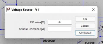
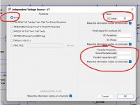
So, V1 is set up as a DC voltage source (like a battery). That one is easy as it is just a single value entered of 30 volts. We have no need to go to the 'Advanced' option for that but we can if we want to.
The advanced option shows 'None' for any AC options and just 30 volt for the DC value.
In LT such a supply is perfect. It has zero impedance and can deliver 'infinite' current.
We could add a tiny amount of series resistance in the options. Say 0.5 ohm. If you do that you will find the supply to the amp is now effected a little by the amp delivering current to the load.
Try it. Look at the DC rail and you will see ripple on it as you add resistance.
V3 at the input simulates a signal source such as a CD player or signal generator.
We have it set to 'Sine' and we want no (0volt) DC offset. Any value we enter for an offset will shift the sine according to the value entered. Try it. Remember the amp will not pass DC as it is AC coupled so look on the actual voltage source itself.
Amplitude is the peak value of the sine you want. I usually set these to give 4 volts peak at the amplifier output which corresponds to 2.83 volts RMS or 1 watt into 8 ohm.
You can either use trial and error or calculate the voltage needed from knowing the gain of the amp.
Frequency is set to 1kHz in this case.
No time delay. Entering a time value here (say 100ms) would mean the input does not start until after 100ms has passed.
Theta I have never used. You can see what it does in attached but you need to alter the sim settings to do this.
Phi or phase. If you enter 180 (these are degrees) you get an 'inverted' sine. Try it. Useful for things that need out of phase signals.
Ncycles. How many cycles the voltage source produces. Leave blank to to free run.
AC amplitude is normally set to '1' but have a read at post #2975 above this one.
Attachments
- Home
- Design & Build
- Software Tools
- Installing and using LTspice IV (now including LTXVII). From beginner to advanced.