Yes. If the dip is not typical of the wider behaviour, then it's best not corrected otherwise your room will see a peak. Better to go with the acoustic flow and find the axis (to listen to) which is better representative of the bigger picture.Look at the off-axis. On-axis will probably be worst for a coaxial. A smoother off-axis design point may be warranted. A small degree off-axis may be the best listening position.
Dave
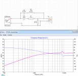
I checked again and it seems the only way an RLC can boost locally an FR is by reducing the overall efficiency. I attached a simple simulation, if R1 is removed the effect of 9k bump disappears.
It is not about if I finally use this boost in my design I just want to clear my knowledge and what is possible.
Can someone suggest what circuit should be used to achieve a boost in FR without reducing the overall efficiency ?
It is not about if I finally use this boost in my design I just want to clear my knowledge and what is possible.
Can someone suggest what circuit should be used to achieve a boost in FR without reducing the overall efficiency ?
Attachments
Hello Pawel,
NO! Passive networks can only "burn" (parts of) the power fed in by the power amp (that's part of what "passive" means). Passive networks can NOT add power to a signal (an amp does this!), so they will always effectively reduce efficiency! ...more or less...
Hoping this is clear enough,
Winfried
NO! Passive networks can only "burn" (parts of) the power fed in by the power amp (that's part of what "passive" means). Passive networks can NOT add power to a signal (an amp does this!), so they will always effectively reduce efficiency! ...more or less...
Hoping this is clear enough,
Winfried
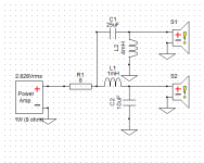
I have a speaker that uses a 25uf cap and 4 mh inductor for a full range driver crossed over at 400hz but this crossover assumes the amp has a rather high damping factor. But I may want to use an amp with a 8 ohm output impedance. No I am not talking about the 8 ohm tap on a tube amp but a SIT amp like is talked about on the Pass forum. Is there an easy way to calculate the new values I need without many trial and error substitutions in xsim ?
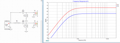
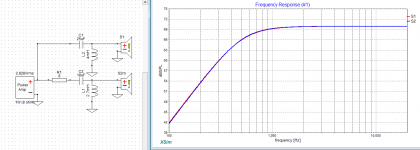
woody, here is one method you might use. The first screenshot compares two default drivers, one has 8 ohms added in series and has the component values adjusted to restore the crossover point. In the second screenshot I increased the level of one driver, just to show that they match.
Attachments
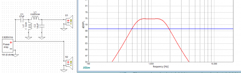
Yes. Resonance can be used to increase output in some cases. Here I have taken two default (70dB) drivers and increased the output of one by 5dB, over two octaves. More power is drawn from the amp and the impedance is lower....more or less...
This kind of approach can also be used to reduce or increase the knee of a low or high pass filter to counter the response of the driver.
Attachments
You're welcome. It's probably obvious but I wanted to point out that when working on a whole crossover you can put the resistance straight after the amp.
It is important to do this because the parts of the crossover begin to interact. Eg: as the driving signal divides between the woofer circuit and the source impedance, the signal presented to the tweeter circuit changes because they are connected to the same point.
It is important to do this because the parts of the crossover begin to interact. Eg: as the driving signal divides between the woofer circuit and the source impedance, the signal presented to the tweeter circuit changes because they are connected to the same point.
Attachments
Question: Is there a donation page?
My passive speakers have been aided hugely by this software, and since I use them in professional environments (or did, before events were cancelled by the virus), it'd be great to give something back.
Cheers,
Chris
Chris,
Thanks. Anyone wants to donate, do it to the Alzheimer's Association. (My wife doesn't have ALZ, but a similar illness. Closest organization I know of).
Alzheimer's Association | Donate to Fight Alzheimer's Disease
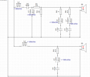
A question about xover resistors - how you would select the power rating for resistors in the xover attached - what are typical rules of thumb for the resistors in the signal path, those across the speaker and in the resonance branches ?
- S2 is mid short/long-term power handling 80W/250W,
- S3 are two woofers 10" in parallel, rated noise power 190W each
- S2 is mid short/long-term power handling 80W/250W,
- S3 are two woofers 10" in parallel, rated noise power 190W each
Attachments
To look at power dissipation in XSim select AddGraph, more, Component Power Dissipation (W). That will display a graph where you can select the components to look at. Then adjust your source (put mouse over source, then press t) to the power level you want. You can also adjust the impedance to match your drivers/crossovers.
IIRC (and someone correct me if I'm wrong) XSim applies the power level equally across all frequencies. In most real music the majority of power is in the lower octaves. So XSim may overstate the power used in the tweeter components. Anyone have more information on this?
IIRC (and someone correct me if I'm wrong) XSim applies the power level equally across all frequencies. In most real music the majority of power is in the lower octaves. So XSim may overstate the power used in the tweeter components. Anyone have more information on this?
Pawel –
Sorry for my much delayed response about your MR18REX. Thanks for posting your XSim .dxo file – it had all the information I needed. You mentioned that this will be a 3-way speaker. I noticed Madisound has a 3-way kit that uses the M18REX. It’s called the CX871 (LINK and LINK) and was designed by Peter Noerbaek of PBN Audio. All the important information is listed: frequency response, crossover components and values, crossover points, individual driver responses and cabinet information. So that’s a great place to get ideas from a respected designer.
You could use the same woofers as the CX871 and duplicate the full design. Done deal! Or you could use the MR18REX portion of the CX871 crossover and use different low end driver(s). The requirements of the low end driver(s) and crossover would be 90 dB sensitivity and a Linkwitz-Riley 24 dB/octave roll off at 300 Hz.
I got intrigued and created a couple of simulations: The first is a sim of the published CX871 MR18REX xover. I did modify your .frd and .zma files (changes explained at the end) for the sim. Some notes:
- The simulation FR matches the published FR quite well with a few small differences. It’s also very close to the CX871 driver roll offs and crossover point at 2100 Hz.
- I used the 20 gauge inductor DCRs per the published design.
The CX871 crossover does have a lot of parts and one very large (5.8 mH) air core inductor. So I created a second simulation based on the original crossover, but with the goal of using fewer, less costly and more standard value parts. Results of this simulation:
- The frequency response, crossover point and driver roll offs are very close to the original CX871 sim.
- The tweeter xover has four fewer parts. Contour shaping parts were replaced with a single resistor.
- The midrange xover has three fewer parts, most notably the 5.8 mH inductor.
My take away is this: While the MR18REX is a nice driver it does take a lot of components to make it shine. Lacking my own measurements I would use the CX871 MR18REX crossover as-is and keep the cabinet dimensions (especially baffle width) and MR18REX volume (~14 L) the same as the CX871. The woofer section could be changed (with a new woofer crossover) as long as it meets the CX871 requirements. I personally wouldn’t replace the woofers unless I had in-cabinet measurements of the new woofer(s). Hope this helps and good luck!
Regarding the input file changes I made (and my opinion about what is important when using .frd and .zma files copied from manufacturer’s graphs):
1. Seas used a 12L closed box when measuring the MR18REX midrange and tweeter responses (stated in the data sheet). This is a very fortunate exception to the normally published Infinite Baffle (IB) responses. Had you started with IB responses (i.e. no cabinet) the cabinet effects shown below would need to be simulated and added/merged with the IB responses to approximate the in-cabinet responses. Lots of important things change when you put a driver in a cabinet! Using the Seas 12L closed box data is close enough for a first sim.
Cabinet Effects = Baffle step and diffraction effects (midrange and tweeter), low end response changes (midrange) and impedance changes (midrange)
2. I created a new midrange .frd file. Your file had a marked response rise from 15 to 20 KHz that I didn’t see in the Seas response graph. It’s a small nit really, but I went ahead and retraced the midrange response.
3. Files copied from response graphs don’t contain important phase data. I used XSim to create phase data for all four files. If you’re not familiar with this capability, here’s how to create phase data:
- Right click on a driver and select the Tune option. Then select the “derived” option in the “FRD phase source” box. In the next window you can define the frequency and slope of the lower and higher tails. Tails are fixed slope extensions to the data that increase the accuracy of the generated phase data.
- To create phase data for the impedance file select the “derived” option in the “ZMA phase source” box.
- To see the FR effects of the phase data: Open one of simulations and perform the above steps for both drivers, but select the “as measured” option instead. Notice the change in the system response without phase data. Then repeat the above steps again and re-select the “derived”options. You’ll then see how I tailed the .frd files.
4. Acoustic Centers: The Madisound information does have acoustic center timing, but it’s somewhat confusing. The tweeter crossover is marked as “-20.87 usec” while the midrange is marked as “Zero Delay”. I would interpret this to mean the tweeter’s acoustic center is actually behind the midrange driver. That’s possible, but I haven’t seen it happen very often. It all depends on how the negative sign is interpreted. This is a small value (0.28” delay) and has a small impact on the simulation. Since I had questions about the value’s sign and the impact is small I just left mod delay set to zero.
Attachments
Last edited:
I really highly appreciate your detailed, insightful and value-adding analysis and comments.
Your improvements to the files are quite useful, they are not attached ? - can you please add them ?
I do not want to sound as a know-it-all and evangelize here but I thought I present my POV as a sort of return for your effort and input as it is based on quite a bit of research using quite unique technical means. I have some distance to 'respected designers'. In particular using 4-th order xovers may look smart but for me is a recipe for a no-chance-for-good-sounding speakers. If I understand it correctly all xovers are 4-th order (I am not very experienced in reading analog xovers, I am a passer-by in this area, my focus is advanced DSP and digital xovers and audio processing).
I do not understand the delays given in this brochure as a 4-th HP has a very different delay than LP.
To me this kind of a xover from a respected designer") very much destroys the key benefit of a coaxial driver - its time alignment. IMO and experience, hi-fi quality is not primarily about FR flatness, neither on-axis, nor off-axis, nor any secret magic combination of them.
very much destroys the key benefit of a coaxial driver - its time alignment. IMO and experience, hi-fi quality is not primarily about FR flatness, neither on-axis, nor off-axis, nor any secret magic combination of them.
It is much more about transients integrity and waveform preservation, especially the attack part. For me of course
But the ultimate verdict is audition, also for my designs, no matter what high tech and calibre advanced arguments I would present here
So I'll finish the xover according to my time alignment preference soon, the boxes are already built, there is also a classical non-time alignment version of xover so when the verdict is known I might let know here
Your improvements to the files are quite useful, they are not attached ? - can you please add them ?
I do not want to sound as a know-it-all and evangelize here but I thought I present my POV as a sort of return for your effort and input as it is based on quite a bit of research using quite unique technical means. I have some distance to 'respected designers'. In particular using 4-th order xovers may look smart but for me is a recipe for a no-chance-for-good-sounding speakers. If I understand it correctly all xovers are 4-th order (I am not very experienced in reading analog xovers, I am a passer-by in this area, my focus is advanced DSP and digital xovers and audio processing).
I do not understand the delays given in this brochure as a 4-th HP has a very different delay than LP.
To me this kind of a xover from a respected designer
very much destroys the key benefit of a coaxial driver - its time alignment. IMO and experience, hi-fi quality is not primarily about FR flatness, neither on-axis, nor off-axis, nor any secret magic combination of them. It is much more about transients integrity and waveform preservation, especially the attack part. For me of course
But the ultimate verdict is audition, also for my designs, no matter what high tech and calibre advanced arguments I would present here
So I'll finish the xover according to my time alignment preference soon, the boxes are already built, there is also a classical non-time alignment version of xover so when the verdict is known I might let know here
Last edited:
Some of the changes (my updated midrange .frd file) are part of the .dxo file. For example, first create a new directory, download the "Madisound CX871 Sim.dxo" file to that directory, open it and then simply exit it. In your new directory you'll see a directory named "!FRD&ZMA" and in that directory another directory named "Data!Madisound CX871 Sim". In that directory you'll find the .frd and .zma files I used. The only one different from the .dxo you posted is "MR18 Woofer Retrace.frd", the re-traced midrange file. In your sim: "Tune" the midrange, navigate to the "MR18 Woofer Retrace.frd" file and select it.Your improvements to the files are quite useful, they are not attached ? - can you please add them ?
Adding the phase data is internal XSim - you'll have to follow the steps in my previous post and add the phase data yourself.
I guess we'll have to agree to disagree on this topic. It sounds like your 1st priority is what I call a time and phase coherent speaker: one that has a nice, smooth step response and can duplicate square waves. The people I most respect in the audio industry place this capability far below the other items you mentioned, but it's a big world! Que Sera Sera.In particular using 4-th order xovers may look smart but for me is a recipe for a no-chance-for-good-sounding speakers. ... IMO and experience, hi-fi quality is not primarily about FR flatness, neither on-axis, nor off-axis, nor any secret magic combination of them. It is much more about transients integrity and waveform preservation, especially the attack part. For me of course
I interpret the delay values as differences in the acoustic centers of the drivers and are independent of the crossover used.I do not understand the delays given in this brochure as a 4-th HP has a very different delay than LP.
How true.the ultimate verdict is audition
Last edited by a moderator:
Disagreement is in most cases a better option It stimulates intellectual effort, creative discussions and may lead to some learning which is for me a key essence of life as a human being.
Well, if the (speaker) frequency response was so overwhelmingly important then digital correction at the signal level and then active xovers would have cleaned the audio market since years. No matter what sophisticated analog xovers you may design it is just a humble fraction of the power you have with DSP.
Why do you think it has not happened yet and the analog audio world holds up fine ?
A question is a bit unfair as this is a specific area of human activity and we are now in the space where more objective criteria like noise level are already no longer on the table and the game has become very nuanced and subjective.
But still it seems the audiophiles converge to some sort of common high fidelity reference ?
One more argument - do you think there is any sginificant correlation between frequency response of most renowned and expensive speakers and their subjective rank ? And it is regularly measured and posted in reviews.
But above all it is only audio, our nice hobby
It stimulates intellectual effort, creative discussions and may lead to some learning which is for me a key essence of life as a human being.Well, if the (speaker) frequency response was so overwhelmingly important then digital correction at the signal level and then active xovers would have cleaned the audio market since years. No matter what sophisticated analog xovers you may design it is just a humble fraction of the power you have with DSP.
Why do you think it has not happened yet and the analog audio world holds up fine ?
A question is a bit unfair as this is a specific area of human activity and we are now in the space where more objective criteria like noise level are already no longer on the table and the game has become very nuanced and subjective.
But still it seems the audiophiles converge to some sort of common high fidelity reference ?
One more argument - do you think there is any sginificant correlation between frequency response of most renowned and expensive speakers and their subjective rank ?
And it is regularly measured and posted in reviews.But above all it is only audio, our nice hobby
Last edited:
Do you measure the impedance of the driver inside the enclosure to use it in XSIM? or the impedance in the datasheet will be adequate?
can anybody light me up about this?
Should the effect of the cabinet on the impedance be taken into consideration?- Home
- Design & Build
- Software Tools
- XSim free crossover designer