I am gearing up (albeit very slowly) to put out a new release of ACD, the Active Crossover Designer tools. These are a set of Excel spreadsheets and templates that allow the user to design multi-way active crossovers (analog or DSP) based on measurements of the drivers in the enclosure. The current release can be found here:
the Active Crossover Designer web page
I've already created a few new additions that will appear in version 3.0. These include:
At this time I am asking for input and requests for other features that I can try and implement. Please post these below or contact me.
.
the Active Crossover Designer web page
I've already created a few new additions that will appear in version 3.0. These include:
- Toggling between digital and analog filter functions in the plots (these are not always the same!)
- Modeling EQ as asymmetric (like analog EQ) or symmetric (like digital EQ a la MiniDSP and Behringer DCX) boost and cut
- A new "settings" workbook that stores the values of program variables.
- Ability to generate IIR biquad coefficients in either MiniDSP or standard formats
- New components that allow the user to simultaneously see on- and off-axis response plots while designing the crossover. Line, surface, heatmap, and polar type plots of the off-axis responses can be generated (plots require the use of GNUplot, a free command-based plotting utility). More info in this thread: http://www.diyaudio.com/forums/software-tools/240961-opinions-wanted-directivity-plot.html
At this time I am asking for input and requests for other features that I can try and implement. Please post these below or contact me.
.
Last edited:
I am considering dropping support for ACD under OpenOffice Calc and would like some feedback.
Calc does a few things very differently, and I am not sure if there is anyone out there running the tools under OpenOffice. Its a pain to maintain two parallel versions unless there is a demand for it. If you run ACD under OpenOffice or LibreOffice, please post or contact me if you would like support for OOCalc to continue.
Calc does a few things very differently, and I am not sure if there is anyone out there running the tools under OpenOffice. Its a pain to maintain two parallel versions unless there is a demand for it. If you run ACD under OpenOffice or LibreOffice, please post or contact me if you would like support for OOCalc to continue.
Be wary of macros!
Not sure what you mean... I don't use a single macro or line of VBA code in the core tools. This is one of the reasons why it has been possible to use the tools in both Excel and Calc. There are a couple of add-ons that use some VBA code to make things easier to do, but they are completely optional for the user. So, there is not really anything to be wary of in that regard.
Last edited:
Hi, please don't drop support for OpenOffice, as not everybody has or wants MS Office. I havn't & neither have lots of other people i know, because we prefer non MS !
Also i'm going to test the FREE Kingsoft office suite Free Office 2013 Download, Free Office Software - Kingsoft Office over the next week or so & see how that fares.
Regards
Also i'm going to test the FREE Kingsoft office suite Free Office 2013 Download, Free Office Software - Kingsoft Office over the next week or so & see how that fares.
Regards
I don't use a single macro or line of VBA code
Any VBA would make it break on the Mac, sonone is good.
dave
Hi, please don't drop support for OpenOffice, as not everybody has or wants MS Office. I havn't & neither have lots of other people i know, because we prefer non MS !
Also i'm going to test the FREE Kingsoft office suite Free Office 2013 Download, Free Office Software - Kingsoft Office over the next week or so & see how that fares.
Regards
Thanks for your feedback. I'm working on some things now and am developing the new functionality in Excel. Later I try to get the same thing to work in Calc. Sometimes this is not possible, and I have to figure out a way to make both work, which can be cumbersome. But as long as I know that the OO version is being used, I will propagate a version for it when new versions are released.
") I'll let you know if it works with KS too
I'll let you know if it works with KS too Hi Charlie,
I too would like to see continued support for Calc, I have this aversion to donating my hard earned $ to Billionaires.
The 3D surface plot looks promising, and so does the new polar type that you're developing with Siegfried Linkwitz. Is it possible to make both types available?
Mike
I too would like to see continued support for Calc, I have this aversion to donating my hard earned $ to Billionaires.
The 3D surface plot looks promising, and so does the new polar type that you're developing with Siegfried Linkwitz. Is it possible to make both types available?
Mike
Hi Charlie,
I too would like to see continued support for Calc, I have this aversion to donating my hard earned $ to Billionaires.
The 3D surface plot looks promising, and so does the new polar type that you're developing with Siegfried Linkwitz. Is it possible to make both types available?
Mike
Thanks for your thoughts. Yes, all of the plots that I show in the thread that I referenced above will be available. Only one of these is natively done using Excel/Calc. For the others, an Excel/Calc worksheet is first used to build a matrix of x,y,z data that the user saves to disk. Then a GNUplot command (*.plt) file is executed to create the 3D plot of your choosing from the matrix data file. This requires that you install GNUplot on your machine, but that's freely available for a wide range of platforms.
You can add "biquad optimizer" to the list of additions to the next version. See:
http://www.diyaudio.com/forums/digital-line-level/257313-biquad-optimizer-iir-digital-filters.html
http://www.diyaudio.com/forums/digital-line-level/257313-biquad-optimizer-iir-digital-filters.html
I had an idea for another ACD extension today: a gain structure manager!
Gain structure refers to the order in which the signal processing units are assembled in the signal chain, DSP or otherwise. Some blocks such as baffle step or open-baffle loss compensation, boost EQ, or high Q filters will have a maximum gain that is greater than 0dB. When levels exceed 0dB in a DSP, some terrible clipping can result so at no point along the signal chain should the output exceed 0dB for an input of 0dB. By carefully choosing the order of filter blocks and the placing any "boosting" stages later in the signal chain, problems can be avoided.
In the ACD design tools there are lots of filter blocks that can be programmed to tailor the driver or system response as the user desires. For each driver, the user can see the overall (combined) response of its filter chain, however, there is not a way to view or analyze every filter block separately, taking into account where it fits into the signal chain, in terms of its impact on the gain structure.
I'm interested in creating a tool that, using VBA, will "scan" through the filter blocks and look for gain structure problems where the 0dB level will be exceeded. It could also suggest a solution, like allowing the user to quickly rearrange filter blocks so that any with "boost" are moved towards the end of the signal chain, or automatically adjusting the gain of earlier stages as needed to bring the maximum level up to 0dB so that signal to noise is maximized.
A tool like this help the user create a DSP loudspeaker crossover that is free from gain structure related problems. It's not just useful for DSP, but for any analog crossover where managing gain structure is of interest to preserve headroom and signal to noise ratio.
If you would be interested in this functionality in ACD, please post your thoughts about it here. Thanks!
I don't know if this has been covered but I'd find it very useful if the biquad section could output coefficients in both standard and MiniDSP format, as has been mentioned, but also if you could specify the number of bits the binary or hexadecimal output converts to.
It has also come to my attention that a number of DSPs work around coefficients that swing effectively between +2 and -2 and yet others work with values that swing between +1 and -1, like a lot of the recent TI MiniDSP on chip products. It would be awesome if the biquad coefficient section had an option to output both sets of coefficient types.
It has also come to my attention that a number of DSPs work around coefficients that swing effectively between +2 and -2 and yet others work with values that swing between +1 and -1, like a lot of the recent TI MiniDSP on chip products. It would be awesome if the biquad coefficient section had an option to output both sets of coefficient types.
Thanks for the thoughts... I would have replied sooner but the notifications from this site are still not working for me.
@Pallas:
I've actually reconsidered the gain structure optimization after considering how I could do it (not simple within Excel) and reading up on the internal architecture of the ADAU1701, currently one of the most common DSP chips. I'm not what TI does, but the ADAU1701 has 24dB of internal headroom about 0dB digital level. It's only at the D-to-A converter that the level must not exceed 0dB, so you just need to make sure that you have a final gain state that keeps the maximum level below this threshold.
@5th Element:
The "standard" form coefficients are actually already in there, just not on the "MiniDSP Biquads" worksheet. If you want, send me a PM or Email and I will tell you where to find them in the current version. But that is a good idea - I can add an option that lets you switch between the two.
As far as the coefficient magnitudes go, I have seen the limit on the TI coefficients mentioned somewhere. I will have to read up on that some more. It's totally normal to have some coefficients that are more than 2 when there is gain or peaking in the filter. You can get the coefficients back into the -1 to 1 range by reducing the gain of that stage. In ACD you do this by entering both the filter type and parameters AND gain on each stage as necessary. Drop me a line if you want an example. This can easily be done manually by the user. I can't easily automate this in ACD unless I use some VBA scripting.
As far as the number of bits, if you mean in the coefficients, these are double type but really you are getting precision from the mantissa only, which is 15-16 decimal places or 52 bits of precision.
UPDATE: The next version of the Active Crossover Designer will support PC-based crossovers under Linux via LADSPA plugins and ecasound.
Many of you know that the Active Crossover Designer generates the "advanced biquad" coefficients for miniDSP crossover products. These can be copied from ACD and pasted into the miniDSP GUI to quickly implement the crossover filters that have been developed for your loudspeaker.
In the same manner, the next version of ACD will generate sets of LADSPA plugin commands for each driver, and for the system, for use with a new 'ACD' LADSPA plugin. To implement the crossover, the user copies the LADSPA plugin commands to a file that is then called from ecasound. Ecasound uses the LADSPA commands to processes the audio stream into several channels and then sends them to an audio output device such as onboard audio, a USB soundcard, or other device.
This represents a major advance in flexibility in that the user can choose to implement the crossover using any computing platform that supports Linux Audio and ecasound, from a powerful desktop system, to a mini computer, to a Raspberry Pi 2 or Beagle Bone Black. By using a computer instead of hardware to implement the DSP, the user also gains all the other features that the computer platform provides.
This joins a list of major feature upgrades that will be available in the next version of ACD. I'm hoping that the new version can be made available in a few months.
I came up with another feature for the next version of ACD: a routing table. A routing table describes how inputs and outputs should be connected.
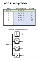
Currently the routing is assumed to follow this topology:
A "staggered" topology can also be used in which:
Woofer crossover & offset
If I add a couple extra slots in the system spreadsheet for more processing blocks instead of just one per driver like I do now, the branching scheme could be modeled, and signal routing implemented with the routing table as shown in the attachment.
In the past when I was considering the miniDSP products only the "parallel" scheme was needed because that's all that the miniDSP can implement. But now that I am planning on implementing LADSPA plugins for Linux based audio, a "branching" scheme is finally possible. As a result it only makes sense to make it possible to model this in the Active Crossover Designer as well.
Feel free to share your thoughts on this. I will add it to the "to do" list and think about how to best implement it a little more.
Currently the routing is assumed to follow this topology:
the signal is supplied to the system and the system filters are applied
the input for driver 1 is the output of the system filters
the input for driver 2 is the output of the system filters
the input for driver 3 is the output of the system filters
the input for driver 4 is the output of the system filters
You can think of this as a "parallel" routing scheme. This is built into some DSP hardware like the miniDSP. I give an example of this in the attachments.the input for driver 1 is the output of the system filters
the input for driver 2 is the output of the system filters
the input for driver 3 is the output of the system filters
the input for driver 4 is the output of the system filters
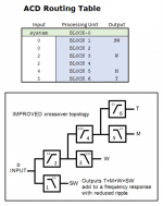
A "staggered" topology can also be used in which:
the signal is supplied to the system and the system filters are applied
the input for driver 1 is the output of the system filters
the input for driver 2 is the output of driver 1
the input for driver 3 is the output of driver 1
the input for driver 4 is the output of driver 3
etc.
This is a branching scheme, and for some types of filters it is superior to the parallel scheme because the phase alignment is better in each channel. SL presents some info on this here:the input for driver 1 is the output of the system filters
the input for driver 2 is the output of driver 1
the input for driver 3 is the output of driver 1
the input for driver 4 is the output of driver 3
etc.
Woofer crossover & offset
If I add a couple extra slots in the system spreadsheet for more processing blocks instead of just one per driver like I do now, the branching scheme could be modeled, and signal routing implemented with the routing table as shown in the attachment.
In the past when I was considering the miniDSP products only the "parallel" scheme was needed because that's all that the miniDSP can implement. But now that I am planning on implementing LADSPA plugins for Linux based audio, a "branching" scheme is finally possible. As a result it only makes sense to make it possible to model this in the Active Crossover Designer as well.
Feel free to share your thoughts on this. I will add it to the "to do" list and think about how to best implement it a little more.
Attachments
After a little more thinking about how the signal flow is organized in and propagated through ACD, I came up with the following architecture that is completely extensible (I think):
PROPOSED (new) ACD DESIGN ELEMENTS:
CHANGES/ELIMINATIONS in the proposed new architecture:
Will no longer support modeling analog active filters (IIR digital filters only)
Global-Settings worksheet will be added to store variables that control global behavior
All behaviors may no longer be identical in OpenOffice Calc (but will hopefully still be supported)
These changes should make ACD both more capable and more flexible.
PROPOSED (new) ACD DESIGN ELEMENTS:
- Each filter is a worksheet to calculate the complex electrical response of the filter
- Each block is a worksheet that groups filter responses
- The Processing Chains worksheet links blocks together into chains (this may employ the routing table concept)
- Each Driver worksheet combines a processing chain with driver data into a driver response
- Each Response worksheet combines (sums) driver responses into a composite response and plots them
- Each System worksheet gathers responses into the system response and plots them
- For systems with fewer bands and that only use a few filter the total number of calculations will be reduced. Currently unused filters are still being calculated in the background and occupy space on the spreadsheet and memory in the computer. Now only the elements that are used are included in the design.
- Because the proposed architecture is extensible, it can also model and number of drivers and very large system. Some examples include:
* a line array
* modeling where to place a number of identical drivers on the baffle to smooth the influence of floor bounce
* loudspeakers with more than four drivers (the current ACD is limited to four drivers)
* one loudspeaker on many axes, e.g. simultaneously modeling and plotting the on axis and off-axis responses
CHANGES/ELIMINATIONS in the proposed new architecture:
Will no longer support modeling analog active filters (IIR digital filters only)
Global-Settings worksheet will be added to store variables that control global behavior
All behaviors may no longer be identical in OpenOffice Calc (but will hopefully still be supported)
These changes should make ACD both more capable and more flexible.
- Status
- This old topic is closed. If you want to reopen this topic, contact a moderator using the "Report Post" button.
- Home
- Design & Build
- Software Tools
- feature requests wanted for Active Crossover Designer tools v3.0