I did some groundwork, investigating the WinISD driver file format to see what it would take to translate to TL format. Lo and behold, it was completely trivial. WinISD .wdr files say, for example,
Sd=0.00375
while TL .lsd files say:
Sd 0.00375
There are three spelling differences: Model vs. Title, BL vs. Bl, and Le vs Lvc. Other than that, all it takes is to replace the = with a blank.
The units appear to be the same.
A C program to do the translation is attached. I expect that letting TL read .wdr files would be a no-brainer - just change the line parser to delimit on = instead of space and accept the alternate names (BL really should be all caps anyway).
Attachments
Sorry haven't had chance to upload the updates yet. Don't have access to a pc!!Didn't see you post above wmb, I have already altered the program to allow it to read wdr files. Thanks anyway though...
I'll upload the update when I get a chance.
Ok i have uploaded 3.6.1.7
When altering a Start/End Area in the Geometry Display Window, holding Ctrl will also change the area of adjoining elements and branches if they originally had the same area
When a new element or branch is created it is now automatically selected.
The driver library can now read .wdr (WinISD Driver) files. We suggest that you copy these from your WinISD directory to your folder library directory as this application will not have permission to write to files in the WinISD folder.
Recently accessed files can now be opened via File -> Recent Files.
I have also setup a twitter account @leonardaudio where I will announce any relevant news/updates. Follow if you want.
No problem! I can easily convert any driver files I need with my program. My intention is just to help you refine your fine program so it's as easy to use as possible. Perhaps you can make a little money from donations or sales or wherever you decide to go with it.
Using TL has already changed the way I think about ported boxes. By moving the port, you can either "pick off" or suppress different cabinet resonances, and by moving the driver you can avoid exciting some cabinet modes. Lumped-parameter approximations are okay for almost-cubic boxes, but when the box starts to look like a pipe, things get more interesting.
Using TL has already changed the way I think about ported boxes. By moving the port, you can either "pick off" or suppress different cabinet resonances, and by moving the driver you can avoid exciting some cabinet modes. Lumped-parameter approximations are okay for almost-cubic boxes, but when the box starts to look like a pipe, things get more interesting.
Another great update, thanks! The new feature work fine.
Are you getting tired of my suggestions yet? In case you aren't, here's another: A control that would adjust the boundary between two elements, keeping the total length of the pair the same. The areas would change along the existing taper lines. If that's not clear, I can try to say it a different way.
The use case is what I have been doing for the last 3 hours - moving ports and drivers to adjust the "pipe resonances". As it is, you have to adjust the left element, then make the inverse adjustment of the right element, and that gets tedious in a hurry.
Maybe it could just be invoked by holding Ctrl while using the length control.
Hi,
Only have my phone to reply on so can't go into much detail but the last update i did had something very similar. If you split an element then you can 'drag' split point between the two elements so the total length remains the same. However this can currently only work with elements that have a consistent taper and can be represented by one element...
Only have my phone to reply on so can't go into much detail but the last update i did had something very similar. If you split an element then you can 'drag' split point between the two elements so the total length remains the same. However this can currently only work with elements that have a consistent taper and can be represented by one element...
Using TL has already changed the way I think about ported boxes. By moving the port, you can either "pick off" or suppress different cabinet resonances, and by moving the driver you can avoid exciting some cabinet modes. Lumped-parameter approximations are okay for almost-cubic boxes, but when the box starts to look like a pipe, things get more interesting.
I was doing the same thing a few days ago. I got a couple of errors, and haven't had time to nail them down, but since you mention it....The use case is what I have been doing for the last 3 hours - moving ports and drivers to adjust the "pipe resonances". As it is, you have to adjust the left element, then make the inverse adjustment of the right element, and that gets tedious in a hurry.
Changing the position of the port does seem to affect the output, and I also found harmonics (esp the 2nd) could be reduced by making two ports, one with a length about half the length of the other one.
Thing is, the results don't match WinISD (the ports are always longer than WinISD predicts) and I'm concerned that TL.app (really, time for a better name) is including the port length in the overall calculations. I also suspect it's seeing the ports as additions to the total volume.
Now, Peter, while that might be a big bear to deal with, our results are flying in the face of what's been "known" for over 30 years - "port position does not matter and two ports always sum as one". If it turns out that our results are right, you could revolutionize bass reflex design. Well, at least add something new to the discussion.
")
To be clear - I think there needs to be a way to make an element internal. That is, not added to the total length, and subtracted from the volume of the element it's associated with.
Last edited:
My preliminary results, which I'm planning to write up formally:
Assume a bass reflex cabinet that is long compared to its cross-sectional area, i.e. essentially a "pipe". It is well-known that closed-end pipes resonate at half-wavelength frequencies. 1/2 lambda, 1 lambda, 3/2 lambda, 2 lambda, etc.
If you put the driver at the point 1/4 of the way down, it cannot excite the 1 lambda resonance, because that resonance has an antinode at the 1/4 point. Then, if you put the port at the halfway point, it cannot emit at any of the N + 1/2 lambda resonances, because they all have antinodes at the halfway point. Thus, in one fell swoop, you eliminate port radiation at the first three cabinet resonances (1/2, 1, and 3/2 lambda), as well as all of the odd-numbered higher-order ones.
The 1/2 lambda (first) resonance shows up in the driver output, but can be pretty well damped by adding short sections of heavy stuffing at both ends.
It works the other way too, with the driver at halfway and the port at 1/4. The 1/4 point for the driver probably works better for positioning the driver at ear level, for most reasonable cabinet sizes.
The "port position does not matter" mantra is correct insofar as the low-frequency extension effect is concerned, but it does affect port radiation at higher frequencies.
Keriwena, I do not share your concern that the port length affects the overall length as far as the base calculations are concerned. I convinced myself by looking at the structure of the high-order peaks in the port output. Those peaks occur at the N/2 lambda points of the overall length. Changing only the port length affects the bass-extension resonance, but does not affect the frequencies of those cabinet-resonance peaks. That is the intuitively-correct result.
It is true that the port length affects the model length that is displayed in the Model Info panel, but I don't see any evidence that that displayed number is itself used in the response calculations.
For a few designs I have tried, TL and WinISD agree very closely with respect to bass extension, for boxes of the same volume and ports of the same area and length. That is especially true when using WinISD's conventional port modeling. WinISD's transmission line port modeling gives somewhat different results, predicting surprisingly-high Q for the bass-extension resonance. I'm not sure I believe WinISD in that mode.
I'm not aware of WinISD having a transmission line mode. As far as I know WinISD using a lumped parameter mass spring model and so does not take into account box or port resonances.
The more pipe like a box is the less accurate this method becomes and the more reason to use a wave-equation based model such as HornResp, MJK's Math cad or TL.app (I know I know, better name is required!)
Wmb, your findings seem sensible...
The more pipe like a box is the less accurate this method becomes and the more reason to use a wave-equation based model such as HornResp, MJK's Math cad or TL.app (I know I know, better name is required!)
Wmb, your findings seem sensible...
Last edited:
Just a few quibbles:
Sometimes, when clicking on an element to select it, instead the drawing jumps back to the original size and position.
The 'drag the split' doesn't seem to work, at least after there's another element attached - it jumps to one position and won't move from there.
The 'Redo' will go 'round the circle, past the last change and produce the original file loaded. You can undo it back to where you were, but it's weird.
Otherwise, the new changes are very helpful. Great work, as always.
WinISD version 0.7.0.900 has a 'Use "transmission line"-model for port simulation" checkbox on its "Advanced" control page. Checking that box shows the effect of resonances within the port tube in the transfer function, and also, as noted, tends to predict different behavior in the bass extension region. That version was never formally released but a link was posted on Linearteam's (now-defunct, spammed out of existence) forum.
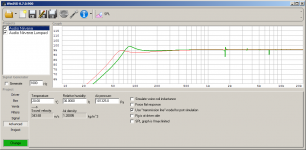
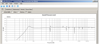
The attachments shows the WinISD and TL models of the same box, driver, and port. It's an Audio Nirvana 8" driver in a 38 liter unstuffed box, 10 cm diameter round (78.5 cm2 area) x 10 cm long (60 Hz) port. The TL model is "boxy", with 929 cm2 area and 41 cm total length.
The green WinISD trace is with the transmission line port model, showing the port resonances starting at 1700 Hz. The red trace is the lumped model.
Adding short sections of heavy stuffing at the box ends on the TL model brings down the port peak so the low-frequency part of the graph matches the red (lumped) WinISD graph quite closely, and also tames the box resonances.
Attachments
The 'drag the split' doesn't seem to work, at least after there's another element attached - it jumps to one position and won't move from there.
The drag split seems to work well on mine. For example:
A sealed enclosure with two elements:
An externally hosted image should be here but it was not working when we last tested it.
Then split the first element in two. Note that the split line is a different colour (This shows that you can drag it)
An externally hosted image should be here but it was not working when we last tested it.
Add a port:
An externally hosted image should be here but it was not working when we last tested it.
You can then drag this split, and thus the port, along the length of the two elements:
An externally hosted image should be here but it was not working when we last tested it.
An externally hosted image should be here but it was not working when we last tested it.
I have the same "jumps to a new position problem", even with no other elements attached. It reproduces easily, in the simplest possible case:
a) Open TL afresh
b) Select the initial element
c) Type S to split it (or use right-mouse, it doesn't matter which)
d) Click-and-drag the mouse on the split line, away from the square handle
At the instant you start to move the mouse after down-clicking on the split line, the split line jumps to the far left, showing "Split ratio 0.01" in the status bar at the bottom of the window. Subsequently, the split position cannot be moved from there; if you attempt to drag it, it just stays in the same position.
This misbehavior is very robust for me, to the extent that I have seen many failures but no successes. I have also tried the two-element-plus-port geometry shown in your report, and it fails in the same way.
Attachments
- Home
- Design & Build
- Software Tools
- Transmission Line Modelling Software