FWIW: I am working on a MLTL where I did extensive measurements (and als sims using MJK's sheets) and there I had to put the woofer near the halfway point of the cabinet to flatten out the 1st harmonic. Measurement in good agreement with the sim. There the port is at the bottom, thus the line sort of extending on the floor below the port
FWIW: I am working on a MLTL where I did extensive measurements (and als sims using MJK's sheets) and there I had to put the woofer near the halfway point of the cabinet to flatten out the 1st harmonic. Measurement in good agreement with the sim. There the port is at the bottom, thus the line sort of extending on the floor below the port
Thanks. I had also built a test box with movable baffle, divider etc. and found the same thing with measurements. My design with the driver at about .4 of the line had much reduced first harmonic too vs Paul suggested placement. Apparently reducing that and smoothest response is not the main goal here?
Does anybody have any experience running the Leonard Audio software on a Mac under a virtual machine running Windows 10? Windows installer and Net Framework 4 are already installed as part of the OS, but I get a message that it can't be installed.
My Windows machine took a dump due to mandatory Microsoft updates.
Thanks
Disregard this, I got it working.
Thanks. I had also built a test box with movable baffle, divider etc. and found the same thing with measurements. My design with the driver at about .4 of the line had much reduced first harmonic too vs Paul suggested placement. Apparently reducing that and smoothest response is not the main goal here?
I didn't see any issues at all with your sim. The out of band port resonances were lower than PK's. IMO that is better. Typically find my alignments to be around 0.38
I've been a bit mentally frazzled today as my recently upgraded to windows 10 computer is now stuck in a unending boot loop.
I don't see it as Paul proved anything by saying the driver needs to be at 1/3. He just said it, but when I model it it doesn't look all they great to me. I know that conventional wisdom is to place the driver between 1/5 and 1/3 of the way from the beginning of the line, but in my modeling, the port resonance between 100-200Hz looks poorly handled. I'm guessing from your statement that LA and Hornresp make it look worse than it sounds and that I shouldn't be all that worried about that..... so what should I be worried about when modeling? What am I looking for?
The driver is the SB23NRX 8". the enclosure is about 50L and the line is about 60" . S0 and SL are 51"sq The speaker is a three-way that'll be crossed around 300-500Hz. This is all for an ML-TL. I also have played with an ML-TQWT that I thought looked pretty good too, but apparently not.
Thanks
Greets!
You're welcome!
Ugh! Sorry, no clue. Computers in general and windoze in particular are the banes of my life.
Again, compare the vent's frequency response to see the difference the driver position made.
AFAIK I've already spelled out everything of interest to do designs along with tech references to help with understanding, so can't think of anything else beyond I prefer to put MLTL drivers between 1/3 - 2/5 [I use math that is 3D Vs MJK's 1D AFAIK solution] as a compromise between the extra damping required at higher locations and lower where there's little/no acoustic vent damping since I was 'raised' at a time when acoustic efficiency was a prime performance goal and just plain prefer the 'sound'/'tone' of such alignments over the historical way of generally heavy damping.
Haven't compared my driver location to MJK's fixed points, but based on sims from several programs pretty confident that fiddling with stuffing density would ameliorate any potentially audible differences, hence my 'don't sweat the small stuff' attitude since most folks reading these forums aren't seeking inaudible measurement perfection, just good-to-excellent performance compared to consumer products, not to mention that driver location Vs 'floor bounce', room vertical eigenmodes and seated ear height is more important WRT in-room performance.
For instance, using MJK's software, I need only 0.2 lbs/ft^3 stuffing density Vs PK's posted 0.75 lbs/ft^3 alignments, an audible difference over a wide BW! Looks great in a sim and no doubt super 'smooth' sounding Vs mine's inaudible fractional dB 'warts', but it's what he likes and apparently his clients too, which is all that really matters.
An interesting side note is that even my minimal amounts proved so often to be too much for enough folks that I quit recommending any, instead posting "damp to 'taste'
") ".
".FWIW I've been designing these tower/column alignments since the mid 60s thanks to building/measuring RCA's Harry Olson's late '40s idea of a 'HIFI' speaker [tall, end loaded tower reflex] and in mine and others experience MLTLs ideally need more net Vb than its reflex cab + vent net Vb for best overall performance, so with your driver requiring a T/S max flat reflex needing nearly its Vas in net Vb with a ~Fs tuning, the MLTL would be a bit larger with a good general rule-of-thumb being whatever it takes to add at least a 3 dB peak at tuning and let the 1/4 WL TL action damp it down.
Anyway, I guessed wrong, yours is a near ideal length for the common ~38" seated ear height MLTL; its very high aspect ratio fooled me. A quick calc assuming no significant amount of added series resistance to raise Qts much puts this driver/height at ~120 L tuned to at least Fs.
All that said, none of this is 'cast in stone', merely based on a ~century's worth of well proven open, closed, conical pipe combined with Helmholtz resonance theory, so ALL speaker alignments are just a point along a continuum from an open driver [open baffle] to a reactance annulled back loaded horn [BLH], ergo within the limitations of the laws of physics one can design to suit the needs of the intended app.
In ~short; the 'rules' can be used to quickly create a good - excellent performing speaker with no need to sim it since damping, vent tuning ideally should be done 'in situ' same as any vented alignment; or just be a starting point to whatever alignment most closely meets the needs of the app.
You've been exposed to the knowledge, the rest is up to you as to how you want to apply it.
Good luck and please do a follow-up of the build, any tweaking required and preferably near-field and in-room 'sweet spot' measurements.
GM
Greets!
You're welcome!
Ugh! Sorry, no clue. Computers in general and windoze in particular are the banes of my life.
Again, compare the vent's frequency response to see the difference the driver position made.
AFAIK I've already spelled out everything of interest to do designs along with tech references to help with understanding, so can't think of anything else beyond I prefer to put MLTL drivers between 1/3 - 2/5 [I use math that is 3D Vs MJK's 1D AFAIK solution] as a compromise between the extra damping required at higher locations and lower where there's little/no acoustic vent damping since I was 'raised' at a time when acoustic efficiency was a prime performance goal and just plain prefer the 'sound'/'tone' of such alignments over the historical way of generally heavy damping.
Haven't compared my driver location to MJK's fixed points, but based on sims from several programs pretty confident that fiddling with stuffing density would ameliorate any potentially audible differences, hence my 'don't sweat the small stuff' attitude since most folks reading these forums aren't seeking inaudible measurement perfection, just good-to-excellent performance compared to consumer products, not to mention that driver location Vs 'floor bounce', room vertical eigenmodes and seated ear height is more important WRT in-room performance.
For instance, using MJK's software, I need only 0.2 lbs/ft^3 stuffing density Vs PK's posted 0.75 lbs/ft^3 alignments, an audible difference over a wide BW! Looks great in a sim and no doubt super 'smooth' sounding Vs mine's inaudible fractional dB 'warts', but it's what he likes and apparently his clients too, which is all that really matters.
An interesting side note is that even my minimal amounts proved so often to be too much for enough folks that I quit recommending any, instead posting "damp to 'taste'
FWIW I've been designing these tower/column alignments since the mid 60s thanks to building/measuring RCA's Harry Olson's late '40s idea of a 'HIFI' speaker [tall, end loaded tower reflex] and in mine and others experience MLTLs ideally need more net Vb than its reflex cab + vent net Vb for best overall performance, so with your driver requiring a T/S max flat reflex needing nearly its Vas in net Vb with a ~Fs tuning, the MLTL would be a bit larger with a good general rule-of-thumb being whatever it takes to add at least a 3 dB peak at tuning and let the 1/4 WL TL action damp it down.
Anyway, I guessed wrong, yours is a near ideal length for the common ~38" seated ear height MLTL; its very high aspect ratio fooled me. A quick calc assuming no significant amount of added series resistance to raise Qts much puts this driver/height at ~120 L tuned to at least Fs.
All that said, none of this is 'cast in stone', merely based on a ~century's worth of well proven open, closed, conical pipe combined with Helmholtz resonance theory, so ALL speaker alignments are just a point along a continuum from an open driver [open baffle] to a reactance annulled back loaded horn [BLH], ergo within the limitations of the laws of physics one can design to suit the needs of the intended app.
In ~short; the 'rules' can be used to quickly create a good - excellent performing speaker with no need to sim it since damping, vent tuning ideally should be done 'in situ' same as any vented alignment; or just be a starting point to whatever alignment most closely meets the needs of the app.
You've been exposed to the knowledge, the rest is up to you as to how you want to apply it.
Good luck and please do a follow-up of the build, any tweaking required and preferably near-field and in-room 'sweet spot' measurements.
GM
Thanks GM and sorry for my late reply; I missed your post in my inbox.
Anyways, It's good to get two slightly different points of view from two experienced designers. Good stuff! And I think I'll tune to taste as you recommend. I'm making the baffle removable, so it should be easy enough.
The driver does indeed need a good sized box, but I believe PK modeled using Meniscus's measurement of this driver. I'd have to hunt up those T/S specs, but I believe they're fairly similar to Zaph's measurements which shows a lower Vas than the Manufacturer specs.
Also, I've stretched my planed enclosure another 7L or so and increased the line length by about an inch, so it's now around 57L and 61" long. I've used LA to account for the differences while keeping the system and port response nearly identical to what PK came up with. That's going to be it though. I really have no desire to put an 8" woofer in 120L box!
Thanks again
Stuffing, Lining Damping confusion (that's me..)
Hello Schmeet,
First of all, THANK YOU for this tools. REALLY impressive, I'm now capable of designing a base model.
I was looking from a distance for years at transmission lines and somehow never got to designing one. UNTILL your tool came along. I've been reading about this creature (TL that is) and understand at least the basic parts of it. So, started designing and ON PAPER, it looks promising.
If I talk ********, feel free to correct
QUESTION:
There seems to be a general consensus about the "magic" part of the TL, being stuffing / lining the TL with damping material and that's the point I seem to get lost. In your tool there is a damping parameter, which holds some default values, from light to heavy damping. I do NOT understand how these number (specified in Kg/m3) relate to the values I find on some damping material.
Heavy (at least the highest value I found sofar in the market) is 30 Kg/m3. Than its lesser heavy version is 20 Kg/m3 and 1 Kg/m3. The lowest I found sofar is 0,8 Kg/m3.
NOW when I use the default values in LA, there is some damping effect visible. But when I use the market values, say 20 Kg/m3, I see REAL effect.
What I do to notice the effect, is split the line in a number of sections, at least a Closed beginning, the offset area for the driver, a mid section and the section at the open end of the line. Then add stuffing to one or more of these sections. Each section has its own effect, which makes complete sense regarding the ¼ wave principle of the line, its open and closed end and the driver offset.
Adding 20 Kg/m3 at the first closed section shows a decrease in SPL in the low end AND a nice roll-off from 100 Hz to the tuning frequency of the line of around 6 dB. It almost matches the infinite baffle line of the driver.
This is supporting a number of articles stating that a good designed TL show this kind of roll-off.
ALSO, adding 10 to 20 KG/m3 at the OPEN end of the line section shows a nice smooth mid-upper frequency range behaviour, removing all the resonant ripples.
THIS makes me wonder, WHAT are your default values and how do they translate in market Kg/m3? Am I using the correct values or not, IF not please clarify
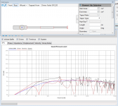
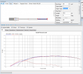
I've added a design picture. It is a small 5 inch Faital Pro driver TL with 4 segments. Kind of the PMC DB1.
First picture is 1 Kg stuffing
Second is 20 Kg stuffing the first segment (half of it to the offset point of the driver) AND complete last segment at the terminus.
Hello Schmeet,
First of all, THANK YOU for this tools. REALLY impressive, I'm now capable of designing a base model.
I was looking from a distance for years at transmission lines and somehow never got to designing one. UNTILL your tool came along. I've been reading about this creature (TL that is) and understand at least the basic parts of it. So, started designing and ON PAPER, it looks promising.
If I talk ********, feel free to correct
QUESTION:
There seems to be a general consensus about the "magic" part of the TL, being stuffing / lining the TL with damping material and that's the point I seem to get lost. In your tool there is a damping parameter, which holds some default values, from light to heavy damping. I do NOT understand how these number (specified in Kg/m3) relate to the values I find on some damping material.
Heavy (at least the highest value I found sofar in the market) is 30 Kg/m3. Than its lesser heavy version is 20 Kg/m3 and 1 Kg/m3. The lowest I found sofar is 0,8 Kg/m3.
NOW when I use the default values in LA, there is some damping effect visible. But when I use the market values, say 20 Kg/m3, I see REAL effect.
What I do to notice the effect, is split the line in a number of sections, at least a Closed beginning, the offset area for the driver, a mid section and the section at the open end of the line. Then add stuffing to one or more of these sections. Each section has its own effect, which makes complete sense regarding the ¼ wave principle of the line, its open and closed end and the driver offset.
Adding 20 Kg/m3 at the first closed section shows a decrease in SPL in the low end AND a nice roll-off from 100 Hz to the tuning frequency of the line of around 6 dB. It almost matches the infinite baffle line of the driver.
This is supporting a number of articles stating that a good designed TL show this kind of roll-off.
ALSO, adding 10 to 20 KG/m3 at the OPEN end of the line section shows a nice smooth mid-upper frequency range behaviour, removing all the resonant ripples.
THIS makes me wonder, WHAT are your default values and how do they translate in market Kg/m3? Am I using the correct values or not, IF not please clarify
I've added a design picture. It is a small 5 inch Faital Pro driver TL with 4 segments. Kind of the PMC DB1.
First picture is 1 Kg stuffing
Second is 20 Kg stuffing the first segment (half of it to the offset point of the driver) AND complete last segment at the terminus.
Attachments
Last edited:
Hi Wae,
I'm no expert, but I found your question interesting so I decided to chime into the discussion anyway.
The way I understand the damping parameter it is simply just a measure of weight per cubic meter.
Say you have a design with an inner volume of 0.1 m3 and the simulation looks good at 3Kg/m3 damping, then you use 3Kg/m3 times 0.1 m3 equals 0.3 Kg damping material. The density of the material itself doesn't matter, you just weight it up. At least that is the way I understand it.
I used this method for my Jordan Eikona 2 design (picture attached), and it works well
Good luck!
Dyrevennen
Hello Schmeet,
QUESTION:
THIS makes me wonder, WHAT are your default values and how do they translate in market Kg/m3?
Attachments
20kg or 30kgs per cubic meter seems extremely dense to me. The box stuffing I have here is light similar to cotton wool, and even a big handful of it doesn't seem that heavy, so I would urge caution on going for anything monster weight. Just because you car will perform ok with 2" taller tyres, doesn't mean it will be happy with tractor tyres on it. There could very well be a point where you start over dampening the sound and stop anything coming out. From what I understand the padding it to act like a shock absorber for the box. Think about a sheet of steel, if you hit it with a piece of wood, it would ring, but put a thin coat of rubber paint on that steel and the ring would be greatly dampened, put a rubber gymnasium floor mat over the steel and hit it with wood and you may not even get a sound out of the steel. The padding also aids to slow the sound wave down slightly but get too carried away and it could potentially stop it.
Hi Wae,
I'm no expert, but I found your question interesting so I decided to chime into the discussion anyway.
The way I understand the damping parameter it is simply just a measure of weight per cubic meter.
Say you have a design with an inner volume of 0.1 m3 and the simulation looks good at 3Kg/m3 damping, then you use 3Kg/m3 times 0.1 m3 equals 0.3 Kg damping material. The density of the material itself doesn't matter, you just weight it up. At least that is the way I understand it.
I used this method for my Jordan Eikona 2 design (picture attached), and it works well
Good luck!
Dyrevennen
Hi Dyrevennen,
Thank you for your reply. I understand what you are telling here. To reverse engineer this, in my first model, it appears 1 - 3 at least are needed to get a good result. Since I know the width of the TL and hight of the damping material, this would give me the amount of material in "length" of the damping material piece. Width x hight is the surface, volume is known for a given weight, so length = volume / surface.
I asked this question because I wanted to work to a "best as possible" starting point in the modeling software and not having to open / change /close the cabinet endlessly. Time is scarce here.
Keep you posted, I may start a thread on this when I know more.
Frans
Hi Silent Screamer,
I hear you. Since I'm new in the TL enclosure business, I wanted to be able to model a good starting point for damping. I've seen pictures of the damping of PMC cabinets, which have a solid reputation. They ALL have serious stuffing, with increased damping at the start of the TL, at the driver offset and around (before) the terminus. Eighter they fool all of us by showing some fake version, or I can learn fro the real deal. I started with assuming the latter.
Since I don't know the density of this stuffing, I don't have a clou as to what the actual damping is. But it sure does not look very light to me. I saw a PMC BB5 picture of (a part of) the inside and it is packed with damping at least 5 cm thick with what looks serious density. It is just a visual observation, NO facts.
I want facts, that's just how I am.
Using LA software, I "experimented" with the damping and noticed that with 20 kg / m3, which is commonly available (just bought 2 sheets, which don't seem that "heavy" at all) and to my surprise the SPL graph was almost exactly the SPL graph of a open baffle with the driver used for the TL. Open Baffle is regarded a good model AFAIK.
I also noticed that using 1 or less for the damping parameter it has effect, but not much.
Would that mean my design is wrong, I cannot imagine it would be completely off, because I followed the TL rules, like use Fs to have a ¼ wave TL line length. Some say use 0.8 x ¼ wavelength, which I also tried and gives good results. Driver offset put at the point where the mid-range "DIP" is the least (somewhere around ⅓ to 1/5 of the TL line). Beginning of the TL is 2x Sd, end is 1x Sd.
Using these gives a very nice rough first version.
Now back to the subject, I would like to understand what I fill in the parameters of the LA software. When I drive my car, some dial says 0 - 240 as the scale and when I drive I can see a needle going up the scale when I put my food more down on a pedal people call a throttle used to increase or decrease your speed. Now, when it reads 50, what is this 50 then (does not feel fast). It appears to be kilometers per hour of time. Now we are getting somewhere. When we all agree that 50 (km / h) is the standard speed in a town, I now where to stop pushing the throttle (at the point where the needle points at 50). I'm sure I use the correct speed through the town.
So when I fill in 1 for damping, what is this 1? I thought it is 1 kg / m3 type of damping in the area I am editing in the LA software. But looking at the default values of LA, 1 should represent "heavy damping". So I enter 1 in damping and my TL still shows some impressive ripples. When I use 3 - 6, it looks much better, when I use 20 it is almost completely smooth (TOO SMOOTH??) and follows the "open baffle" graph.
Looking at terminus speed, it still is way above zero. It looks like the terminus is still driven, terminus output nicely rolls off from the tuning frequency upwards. So all looks OK, but I DON'T KNOW.
I also read that the terminus, opposed to the Bass Reflex is not intended to produce a big wave front, the idea of the TL and its terminus is to provide optimal damping to the driver making it work in the optimal working environment and producing cleaner and tighter bass.
Again I hear what you say, but I still have no clue as to how to use this parameter to work on a "optimal" first model. It is way easier to play with the parameters in software, opposed to open / change stuffing / close / test / open / change stuffing / close and so on.
kind regards,
Frans
Last edited:
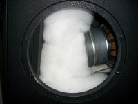
I'm not using the software in question, but I can probably shed some light on some of your questions. Firstly a couple of pieces of dampening are not going to weigh all that much, and that could very easily be quite deceptive. Remember the weight of a single piece that is 1000mm long by 1000mm deep and 1000mm high is only going to weigh 20kgs, so if you only have a few pieces think how much of a small percentage that is of a cubic meter (1000mm x 1000mm x 1000mm) and then times that percentage by 20kg and you will find the pieces you have aren't meant to be that heavy. The problem with dealing with something as light as cotton wool is that it is hard to gauge the weight of it properly. If I was to try and guess how much a cubic meter of the stuff I had was I would say maybe less than 5kgs.
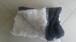
You will find some stuffing / wadding / dampening (has many names) varies a bit, the stuff I have is black on one side that is slightly more dense for gluing to the cabinet, and the inside is white. Have a look at the photo I have attached (for reference the floor tiles are 450mm x 450mm) this piece which is folded a couple of times might weigh 100 grams.
The other thing I have learned with modelling software is you need to respect the parameters... For example you can have a single driver that works well in a .3 cubic meter box, but you keep trying to make the box bigger and bigger until you get the box looking better on paper, but you are now at 20 cubic meters, there comes a point where practicality gets in the road of modelling.
Think about what the padding is going to do to the sound. A box with padding has to sound different to a box without it, it would be an impossibility for it not to. You want enough padding to get rid of any unwanted characteristics like the steel example I gave, but you don't want so much that it alters the sound of the driver.
From what I have previously seen in modelling software, the padding reduces the size of the box and the more you use, the easier it would be to drift from the original design because a large portion of the time that is spent on the modelling software is geared towards making the box model like it is supposed to. The padding is an added extra and from a coding perspective will simply be a variable parameter that may very easily get further and further wrong as more is used.
Now how the stuffing works. In free air sound has very precise measurements i.e. 20Hz = x precise meter wave length, 30Hz = y precise meter wave length, but adding stuffing means there is a physical item now in that free air path and any time sound comes into contact with an object it is absorbed, think empty tile room verses a carpeted room with furniture. Same room size (can even be the same room) but very different sound because the carpet and furniture is absorbing sound waves and slowing them down.
Inside your cabinet is no different. So you don't want to be relying too heavily on the stuffing to get the right curve, you need to have the right box to do that, and just use a small amount to control any nasty reflections inside the box that are going to harm the overall sound. I hope this makes sense.
Yes some places do need different quantities but this just adds to the complexity of modelling the cabinet properly. I would advise against trying to dampen any cabinet to the point it looks smooth because you can bet it will severely dampen the sound that comes out. Unfortunately the padding will alter the size of the box needed, and you do need to make some consideration because of that, and you cant just add more or less like you can your coffee, but I would stay on the conservative side.
Attachments
Last edited:
I forgot to answer the part about the dampening of "1". It really depends on the program as to what they mean by this. I do some coding and I might make it mean several things. But before I wander off tangent is there a kg/m3 next to the value of 1 or is it just a 1?
If it is just a 1, if I was coding it I could make that to mean 1%, some arbitrary value I assigned to 1, or I could make it so 1 meant 100% or full on. It would depend entirely on where my train of thought was, but if I put a weight/ volume after the text box it would be a specific value.
If it is just a 1, if I was coding it I could make that to mean 1%, some arbitrary value I assigned to 1, or I could make it so 1 meant 100% or full on. It would depend entirely on where my train of thought was, but if I put a weight/ volume after the text box it would be a specific value.
To add some context to the subject of stuffing I have actually owned speakers on the two extremes of this subject.
The first was a sealed subwoofer with two passive radiators that was absolutely packed full of padding, to the point where it was nearly touching the driver. Since the box was sealed with no sound flow outside the box (through a port) this was not a major consideration how all this padding would affect the sound, and it actually helped to make the box work like it was a much bigger box without changing the physical size. In this instance where you are trying to control all the sound trapped inside the box padding is your friend.
The other example was another set of Sonus Faber speakers that were full range ported floor standing speakers, and the padding in those was very minimal, for the reasons I mentioned earlier.
Attachments
Focus on one, being blind for the rest....
Hi Silent Screamer,
Your replies have been very helpful in more than one way. I was so focused on trying to tame the reflections, that it never even crossed my mind that this is just ONE aspect of damping. How it all sounds can most likely never be simulated or seen by a graph.
Other parts of your replies made me think a little different. Since the modelling software can "split up" the line in as many parts as you like, may be a better approach is to start with the barely minimal stuffing as a start. Design a TL as 1 line without any bends, split it in segments of say 20 cm over the complete line, a section at the driver location and a section at the terminus to be able to choose on each section to apply damping AND how much.
I found that stuffing placed e.g. at the beginning (closed end) of the line controls the lower (under 100 Hz roughly) of the TL. The usual big dip in the 100 - 200 Hz area can be tamed by driver offset, so no damping required here. The ripples in the "higher regions are (as far as I understand from reading) the result of standing waves / resonance. Since the SPL graph shows dips and bumps at frequencies that are visible IN the graph, it is easy to find the first order spot in the TL (¼ wavelength of the resonance freq.). A bump can be tamed by putting some damping at that spot in the line, if it is a serious bump.
The damping at the last say 1/5 part of the line near the terminus also dampens the ripples. This wil result in just a few spots with damping material. Question is still of course, which type of material and how much, but that I could experiment with by making one side of the TL removable to add or remove stuffing and listen to the effect.
By having all the sections of the TL, I could choose where to apply for What reason.
OOHH by the way, as of your question, the parameter I set to 1 is labeled Kg / m3 so weight of the stuffing / type of stuffing specified by weight (density?). The code should hold formulas of the effect of damping to that area, which is basically my questions, WHAT do you code here. The amount of stuffing, the density of the stuffing or.... If it is density, then 20 x 20 cm (0,2 * 0,2 meters) of damping material with a density of 20 Kg / m3 I currently have (it's 0,04 meters thick) weighs slightly more than nothing, 3,2 gram to be precise (0,2 * 0,2 * 0,04 * 20). Filling the complete line of 2 meters with 20 Kg / m3 for a line 20 wide would result in 32 gram of damping (10x the 20 x 20 cm amount). That's not really the whole world.
Since you need to specify the width of the line as a contant and depth and length of the density this may well be the case here, So that parameter would be type of damping material by density. I hope I get an answer from SMEETH as the programmer of this tool. Maybe you could have a peek at it, it free (donations are appreciated).
AGAIN, Thanks for you replies, much helpful.
kind regards,
Frans
p.s. I may start a thread on TL damping and go to the whole above routine to find a "best practice" TL damping, a best guess starting position". Could well be the title of the thread
Feel free to jump in
I quick installed the program to have a look at it, since it is years since I last looked.
And yes it specifies the weight of the stuffing in kg/m3, and the amount used in m3, but weight and density are not necessarily the same thing.
I have looked at several pieces of modelling software and I have found that the stuffing parameter can have from a minimal affect to a huge affect depending on what the programmer coded.
The problem is there is no such thing as a standard stuffing and what you use can make a difference even if it is modelled perfectly.
Let me explain, we both have hair on our heads (or at least I do and I assume you do) I have very fine hair whereas you might have very course hair, therefore my hair might weigh half as much as yours (or less) but I might have twice as much, meaning that our hair has the same weight, but because I have more hairs on my head I am probably less likely to get a sunburned head.
Stuffing can be the same, remember our ears work by picking up vibrations on tiny hairs in our ears, what is to say if the stuffing that is super fine, might act differently to stuffing that is course, even if it has the same weight per cubic meter?
It is for this reason I would aim to design the box with the absolute minimum stuffing so any variation has a minimal affect on the final response. When it has all been said and done and measurements taken you might still want to have a play with different quantities simply to see if you prefer the sound.
Some useful related info:
http://www.pitt.edu/~szekeres/resonant.txt
Sub Box Polyester Fiberfill
http://www.bobgolds.com/AbsorptionCoefficients.htm
GM
http://www.pitt.edu/~szekeres/resonant.txt
Sub Box Polyester Fiberfill
http://www.bobgolds.com/AbsorptionCoefficients.htm
GM
Hi Dyrevennen,
Thank you for your reply. I understand what you are telling here. To reverse engineer this, in my first model, it appears 1 - 3 at least are needed to get a good result. Since I know the width of the TL and hight of the damping material, this would give me the amount of material in "length" of the damping material piece. Width x hight is the surface, volume is known for a given weight, so length = volume / surface.
I asked this question because I wanted to work to a "best as possible" starting point in the modeling software and not having to open / change /close the cabinet endlessly. Time is scarce here.
Keep you posted, I may start a thread on this when I know more.
Frans
My pleasure.
I think LA tells you the internal volume based on your design, it is not necessary to calculate it manually. Once again, based on the damping material density in your simulation, just multiply with the volume LA tells you about your design, and, presto, you know how much material you need. Now you can measure with a scale.
In my experience, 1-3 kg M3 is about right. I agree with some of the other people here, 20 Kg/M3 sounds way too much. One of the benefits of a TL is that it offers a deeper bass (albeit with a steeper rolloff) compared to infinite baffle. For me, this is exactly the reason I love a well designed TL; it plays in a relaxed, resonant free manner. Super sexy
Good luck, and keep us posted!
Guys,
Thanks for your contribution. I've been fiddling around with LA and tried to read and understand the TL papers from King and others.
I think I came up with some nice ideas to get some-one like me starting with a TL design. The damping as we discussed has some remarkable features and behavior, that can help damping in a minimal fashion. That is IF you know what does what where, which is the whole story of DIY audio in the end. I found a very easy to figure out where to put damping to fix a "hot spot" in the TL. By applying 2 or three peaces of damping along the line, I could get a very promising frequency chart It would fix the bad spots almost without ruining the character. Well...., on paper that is
I know, I never started the TL because some experts said "well it's all to the ears of an expert to make damping work well in a TL. If you do it wrong it may sound horrible" and some of it will be true. Saying this to someone who wants to have a go, is not very stimulating is it. Specifically, if you know that there are very solid design starting points / rules for any type of cabinet including a TL. Some of this type of "woble gable" is more marketing hype than facts. I've seen DIY members that build Synergy horns, considered to be "the impossible of the world". OK, took some time to figure out, design and buils, but still, it IS possible. If it's not in 1 head, than it surely is in 200 combined heads......
I think that it IS possible to have a set of "best practices" for the design of a TL, INCLUDING how to dampen the TL. This would mean if you know your driver and apply those best pratices, you have a good first version of a TL, build it and that you can further tune to your likings.
To test this, I just selected a driver, used the rules, put it into LA and got the first version, appearing much like Kings versions. Than applied the damping rules, which as far as I found out so far ALWAYS focus mainly on 3 area's of the TL, that shaped the SPL curve the way I think would sound nice. All in 10 minutes, than changing some details "et voila" a nice candidate for saw dust in 30 minutes to an hour. I need to saw some dust now, since I have the drivers available. The TL is a simple tower version 2 fold (including the terminus part) like a PMC FB1. Also did a BB5. which took more time, but still. I don't care if it is internally the BB5. Gives me a rock solid 300 Watt TL, hope it sounds like it looks on paper.
Since there are a lot of damping materials available, we need to figure out a way to define their behavior and resulting sound (IF possible).
I will start a new thread called "TL design best practices for the novice" or something like that. It should help the whole community to better understand and start building TL's.
Topics;
- Drivers
- First design
- Damping
- Passive filters
- Active & DSP
- materials and construction tips
Thanks for your sharing.
kind regards,
Frans
Thanks for your contribution. I've been fiddling around with LA and tried to read and understand the TL papers from King and others.
I think I came up with some nice ideas to get some-one like me starting with a TL design. The damping as we discussed has some remarkable features and behavior, that can help damping in a minimal fashion. That is IF you know what does what where, which is the whole story of DIY audio in the end. I found a very easy to figure out where to put damping to fix a "hot spot" in the TL. By applying 2 or three peaces of damping along the line, I could get a very promising frequency chart
It would fix the bad spots almost without ruining the character. Well...., on paper that is I know, I never started the TL because some experts said "well it's all to the ears of an expert to make damping work well in a TL. If you do it wrong it may sound horrible" and some of it will be true. Saying this to someone who wants to have a go, is not very stimulating is it. Specifically, if you know that there are very solid design starting points / rules for any type of cabinet including a TL. Some of this type of "woble gable" is more marketing hype than facts. I've seen DIY members that build Synergy horns, considered to be "the impossible of the world". OK, took some time to figure out, design and buils, but still, it IS possible. If it's not in 1 head, than it surely is in 200 combined heads......
I think that it IS possible to have a set of "best practices" for the design of a TL, INCLUDING how to dampen the TL. This would mean if you know your driver and apply those best pratices, you have a good first version of a TL, build it and that you can further tune to your likings.
To test this, I just selected a driver, used the rules, put it into LA and got the first version, appearing much like Kings versions. Than applied the damping rules, which as far as I found out so far ALWAYS focus mainly on 3 area's of the TL, that shaped the SPL curve the way I think would sound nice. All in 10 minutes, than changing some details "et voila" a nice candidate for saw dust in 30 minutes to an hour. I need to saw some dust now, since I have the drivers available. The TL is a simple tower version 2 fold (including the terminus part) like a PMC FB1. Also did a BB5. which took more time, but still. I don't care if it is internally the BB5. Gives me a rock solid 300 Watt TL, hope it sounds like it looks on paper.
Since there are a lot of damping materials available, we need to figure out a way to define their behavior and resulting sound (IF possible).
I will start a new thread called "TL design best practices for the novice" or something like that. It should help the whole community to better understand and start building TL's.
Topics;
- Drivers
- First design
- Damping
- Passive filters
- Active & DSP
- materials and construction tips
Thanks for your sharing.
kind regards,
Frans
Question regarding TL software and driver offset.
In an MLTL.... example: Tabaq - parallel pipe with smaller port at the end.
To achieve suppression of the 3rd harmonic, the software indicates that the driver has to be further along the pipe (relatively) than with a simple open ended parallel pipe.
However, the software indicates that suppression of the 5th harmonic occurs exactly at 1/4 of the main pipe length.
I can't reconcile the two cases. Comments on the forums seem to indicate that the 3rd harmonic needs to be further down the pipe in the MLTL case. If that's accurate, then surely the 5th also moves?
J.
- Home
- Design & Build
- Software Tools
- Transmission Line Modelling Software