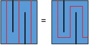
Both ways will do. As long as you do not change dimensions an path length, you can segment the first proposed design in any way you want. I've just simulated default driver in both ways (3 and 5 segments) by changing angles of segments by 90 degres to each other, as well as stright, and there is no diference.
If you look at the paths of the segments, it stays the same no matter how you fold it.
If you look at the paths of the segments, it stays the same no matter how you fold it.
Attachments
I'm struggling to get to grips with the enclosure building process.
Greets!
Did you figure it out?
GM
Has anyone successfully been able to run the software on Linux using WINE? Thanks in advance.
I tried and I tried, but no real success. If I got it to run, something always crashed it. Was one of the reasons I installed back windows after 5 years of linux. Sucks. And sketchup.
Has anyone successfully been able to run the software on Linux using WINE? Thanks in advance.
I tried on a Mac, and it almost worked. The thing that didn't work was the plots :-/
I also ended up going back to Windows for all simulations.
I tried and I tried, but no real success. If I got it to run, something always crashed it. Was one of the reasons I installed back windows after 5 years of linux. Sucks. And sketchup.
Yep. Same issue here. I will have to install it on my Windows machine. Thank you.
Hi, I've just started using this software and I think I've gotten the hang of it pretty quickly. Thanks to Leonard Audio for letting us use it!!
I'm having a bit of a problem though. I find the enclosure schematic kind of confusing and I think I must be using it wrong because I only get proper damping of the upper harmonic peaks when I stuff the larger, open end of the tapered line. My understanding is that I should be stuffing the narrower closed end.
My confusion may be that the enclosure schematic looks like a long triangle on the screen, but it's my understanding that what is shown by default is the front (baffle) of the enclosure. Shouldn't the front baffle be shown as a rectangle with the tapering line only visible from the side? I assume that the long triangle is the full tapered line and I'd section(split) that where I want to fold it or stuff it, right? Please correct me if I'm wrong here.
What I'm trying to model is a folded ML-TQWT with a single driver. Any help here would be greatly appreciated.
Thanks,
Evan
Hi
The enclosure window is not an actual representation of the enclosure. It is a representation of the dimensions of the 'line'
The front and rear buttons on the enclosure window refer to enclosures behind and in front of the driver.
Have you left the wide-end open or have you mass loaded it with a port?
Robert
Hi
The enclosure window is not an actual representation of the enclosure. It is a representation of the dimensions of the 'line'
The front and rear buttons on the enclosure window refer to enclosures behind and in front of the driver.
Have you left the wide-end open or have you mass loaded it with a port?
Robert
OK, that does clear it up some. Thanks. I've closed the line and mass loaded it with a port placed a few inches from the large end. I'm actually getting what look like good results and by stuffing the narrow end I do get reduction in the upper harmonic peaks, but it also quickly reduces bass output around fb. By damping the large end, especially heavy stuffing on the opposite side of the port from the driver I seem to get the best results.
Also, no matter how I stuff it, the impedance still resembles a lined/stuffed BR alignment. Shouldn't it have more of a single damped impedance spike?
Also, no matter how I stuff it, the impedance still resembles a lined/stuffed BR alignment. Shouldn't it have more of a single damped impedance spike?
If the software is giving results similar to real life, that will only happen if you damp it till aperiodic which gives little or no bass reinforcement.
dave
PS: you are designing a ML-Voigt?
If the software is giving results similar to real life, that will only happen if you damp it till aperiodic which gives little or no bass reinforcement.
dave
PS: you are designing a ML-Voigt?
Alright, I had read that you should see mostly a single peak, not a well defined double hump.
I believe a Voigt comes to a point. I'm designing the narrow closed end with a surface area of about SD (100 cm2) and the open end about five times this. I think this would be a ML-TQWT
Have you seen this page describing the properties of the various types of Quarter Wave Resonators? It might help you.
Yes, thank you for that! Haven't read it all yet, but some things are clearer already.
Alright, I had read that you should see mostly a single peak, not a well defined double hump.
Not often. I suspect that even the Bailey line has dual impedance peaks as he claimed bass extension.
I think this would be a ML-TQWT
ML-TQWT = ML-TQWP = ML-Voigt.
Because of some controversy over taper nomenclature ML-V is a less confusing term.
dave
Not often. I suspect that even the Bailey line has dual impedance peaks as he claimed bass extension.
ML-TQWT = ML-TQWP = ML-Voigt.
Because of some controversy over taper nomenclature ML-V is a less confusing term.
dave
Ok, then ML-V. That link does say that you will see a double hump.
Also, in that Bob Brines paper, he sets s0 to .1*sd. Martin King states that it should never be smaller than sd. He calls it throat area, I believe they're the same thing. Do you know what's more appropriate as a starting point?
Thanks
Interesting, my TDL T-Line3s fall into the negative taper class, the port is about 50% of the driver areaHave you seen this page describing the properties of the various types of Quarter Wave Resonators? It might help you.
ML-TQWT = ML-TQWP = ML-Voigt.
Because of some controversy over taper nomenclature ML-V is a less confusing term.
Indeed, until a 'sticky' list of definitions that all will follow is done, need to add ML-horn as a technically more accurate = to ML-Voigt than ML-TQWT, etc., as TQWT more often has defined an inverse [not negative] tapered TL, ergo should continue to do so in vented [ML] form
") .
. MJK did us no favors by not differentiating between the tapers since it's not done in electrical circuits
.I like the 'lumped' ML-V, though while newbies may at least be aware of TLs, there will be no clue as to what it might refer to unless a search turns up this thread or similar.
GM
- Home
- Design & Build
- Software Tools
- Transmission Line Modelling Software