Power Compression Option
I asked before about the possibility of adding this option in, but at the time i don't think it wasn't doable ? Well i've been trying to get my head around AkAbak a bit more & on perusing one of the included PDF manuals, i saw this.
Could you take a look at it please, & see if there is anything similar that TLMS could make use of etc, in order to allow this feature. As well as including the temperature coefficients of copper, aluminiuim could also be included
I asked before about the possibility of adding this option in, but at the time i don't think it wasn't doable ? Well i've been trying to get my head around AkAbak a bit more
& on perusing one of the included PDF manuals, i saw this.Manual Ak21 Exercises.pdf
Page # 27 Exercises
Analyzing temperature-dependent voice coil resistance
Finally, we will analyze the effect of the voice coil temperature on the curve for the acoustic pressure. Please open the script Ex_22.aks.
Could you take a look at it please, & see if there is anything similar that TLMS could make use of etc, in order to allow this feature. As well as including the temperature coefficients of copper, aluminiuim could also be included
This is a double chamber reflex, modelled after a real speaker that was constructed and tested, and gave substantially what this simulator predicts. Posting just to make sure I'm correctly simulating the box as in the picture


View attachment file tlp.zip
View attachment file tlp.zip
Hi Mosquito,
thanks for sharing this design.
I wonder - since the response curve looks much better than the MJK MLTL designs - does double chamber bass reflex really have an edge against transmissionline?
I have been searching in vain for reports where people have tried both against each other.
I also optimized your model a bit:

View attachment DCAAVoptimized.zip
Cheers,
A.
thanks for sharing this design.
I wonder - since the response curve looks much better than the MJK MLTL designs - does double chamber bass reflex really have an edge against transmissionline?
I have been searching in vain for reports where people have tried both against each other.
I also optimized your model a bit:
View attachment DCAAVoptimized.zip
Cheers,
A.
FWIW, I just now highlighted this link, then right clicked and clicked on 'go to HTTP... and it downloaded: http://www.leonardaudio.co.uk/software/TransmissionLine.application
GM
GM
if i want to simulate two of them in series in a TL
IME driver position is important in a tuned pipe of any sort. How do you model for optimum driver Z with two drivers? Find Z for the theoretical twin driver, then, when moving into the physical realm of the build, mount the drivers straddling Z? What about tapered TL bipoles? Model once for the front driver, then for the rear mounted driver then combine the response graphs?
modelling a given shape.
Hi forum,
I just started to use the TL software by Leonard a few days ago, and it is brilliant! Thanks a lot for the effort
So, a question. Is it possible to model a backloaded horn with the shape of the attached figure using the software? I got the drawing from the manufacturer, and would love to compare their design with my own, more conventional TLs, before committing my self to wood
Thanks a lot
Attachments

Hi guys,
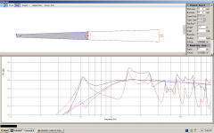
I started to play with this software today, and must say I find it pretty simple... Anyway I would like to check with you if I got it right or at least partially right.
As an exercise, I tried to model the popular "needle" enclosure design with Visaton FRS 8. Since there are no folding examples in the tutorial, I played with it anyway, and this is what I ended up with...
The plan I used to make the model:
And the plot I get is in the attachment.
Although it goes pretty low, it looks kind of "choppy"...
Is this model okay and representative, or can anyone tell me what I did wrong?
I started to play with this software today, and must say I find it pretty simple... Anyway I would like to check with you if I got it right or at least partially right.
As an exercise, I tried to model the popular "needle" enclosure design with Visaton FRS 8. Since there are no folding examples in the tutorial, I played with it anyway, and this is what I ended up with...
The plan I used to make the model:
An externally hosted image should be here but it was not working when we last tested it.
And the plot I get is in the attachment.
Although it goes pretty low, it looks kind of "choppy"...
Is this model okay and representative, or can anyone tell me what I did wrong?
Attachments
Peroz i did one to i believe somehwere int this topic to confirm i got the idea look it up and compare
So sorry I didn't use the search function before posting, but then again, it probably doesn't hurt to debate a little more.
My plot looks a lot like yours and other people's, maybe just a bit different because I did it for the Visaton drivers.
I, too, hear that needles sound notthing short of fantastic, and that's why the choppy plot looks so puzzling... I guess I'll just have to make these needles and hear for my self.
I'm still not sure about the proper way to "make the turns" when creating a model. When calculating the line length, one should draw the center line (in the corners also) and then measure it, but I'm not totally sure how to model the damn thing.
- Home
- Design & Build
- Software Tools
- Transmission Line Modelling Software