Hi,
I use a Behringer UCA222 USB interface, which is supposed to be full duplex and has 2 channels, input and output sections.
I'd like to have HolmImpulse read the voltage at the input of the UCA222, which would be the voltage accross the 8ohm resistor in series with a driver. I'd export the voltage vs frequency data to a spreadsheet to convert to impedance vs frequqency, much like I do manually.
It did not work when I tried and I'm not certain why. One thing I'm not sure of is, where you choose the I/O devices, there is no distinction between the input or output "section" for "USB audio codec", much like how I can set the microphone for the ouput device (I don't know why this is allowed). So I am not even certain it even tried to read the UCA222's input.
Is this even feasible?
IG
Better late than never!
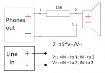
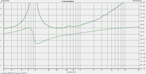
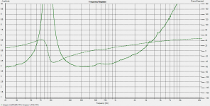
I was playing around and arrived at a solution how you could achieve that. Basically you connect a circuit like it is drawn and measure voltage drops across resistor and driver. These 2 plots will have to be manipulated by introducing a division of these two responses, driver voltage drop being in the nominator part of the fraction. HolmImpulse calls it C=A/B. Once you are done with that, remains to multyply the result by 15, and that means you would have to increase the resulting response by +23.52 dB. This comes from:
spl=20*log(15)=23.52dB
Now this resulting response is your impedance in dB, and in order to appear in ohm is needed this:
Z(ohm)=10^(Z/20); Z being you end result of measured impedance in dB.
Funny though, HolmImpulse can switch the amplitude scale from dB to linear scale and that is actually your Z in ohms. Still, the exported file will be in dB, so it needs a little work on the file to appear in ohms.
There has been a thread on Behringer uca 202 having issues with measuring impedance because of the capacitor in the sound card, so its own impedance rise at low frequencies adds to the one of the device under test. Perhaps doing the impedance measurements this way, will make this sound card a little more practical.
0 dB in the plots equals 1Vrms.
Attachments
you can measure impedanz also with SATlive SATlive Audio Measurement Software
Hey Lojzek,
I was thinking of that scheme, but could not get the measurement as an input for the UCA222 for some reason. I don't think I looked into the issue much further.
In any case, shortly after my OP, I ended up using ARTA/LIMP and the recommended jig for my impedance-measuring needs.
I was thinking of that scheme, but could not get the measurement as an input for the UCA222 for some reason. I don't think I looked into the issue much further.
In any case, shortly after my OP, I ended up using ARTA/LIMP and the recommended jig for my impedance-measuring needs.
- Status
- This old topic is closed. If you want to reopen this topic, contact a moderator using the "Report Post" button.
- Home
- Design & Build
- Software Tools
- Measuring loudspeaker impedance with HolmImpulse - possible?