I think the matched filter approach could be very useful in practice, since even with a non-perfect estimate of the LF response used to calculate the "flipping filter" there is significant improvement, as the residual error in the late IR tail will be close to zero, opposed to exactly zero for the ideal case. The closer to zero (compared to the original IR), the less information is lost when truncating the modified IR before the reciprocal processing is applied to get the actual IR. Which is the key point of the approach: to lessen the impact of the truncation to the reflection-free part of the IR by a proper emphasis/deemphasis cycle.
And, I think it would even be possible to iterate the filter with a best fit strategy, starting with a good estimate (and a reasonably good estimate can sure be found when modelling the box with a good software after having measured the driver properly. With one's own designs this target data is known/given anyway).
I find a very good way to look at any IR is a 3D-plot of its S-Transform (view adjusted to get maximum info). Reading a CSD (let alone plain IR) I find witch magic, compared to that.
- Klaus
I am quite used to looking at CSDs, but am interested in the S-transform you have mentioned. However, I can't seem to understand what units it's displayed in. Does it have anything to do with S-transform of linear equations that are common in control system modeling?KSTR said:
...
I find a very good way to look at any IR is a 3D-plot of its S-Transform (view adjusted to get maximum info). Reading a CSD (let alone plain IR) I find witch magic, compared to that.
- Klaus
Hi soongsc,soongsc said:I am quite used to looking at CSDs, but am interested in the S-transform you have mentioned. However, I can't seem to understand what units it's displayed in. Does it have anything to do with S-transform of linear equations that are common in control system modeling?
I'm only a user of Dr. Ulrich Brueggemann's free S-Transform Viewer, available on his website, www.acourate.com. I cannot comment on math details of the S-Transform. The difference to CSD is very clear nevertheless, as CSD are consecutive properly windowed FFTs shifted in time along the IR, but each of these FFTs are still either quite "blind" regarding time info (when using long FFT blocksizes) or lacking LF frequency resolution (with short blocks). Which makes the CSD-plots so VERY dependent on the parameters used, FFT-size and even more to the window applied (usually asymetric, quick "nose" and longer "tail" parts). S-Trans has both good time and good frequency resolution.
The units in the plot used are frequency and sample# (time) for the XY-plane and level in dB for the Z-Axis. The graphic frontend is excellent, though you need to dig into many parameter details to obtain clean plots. At the moment there is no option to normalize time axis to periods, although this is possible, theoretically. When looking for delayed reflections this isn't useful anyway but it gives more compact plots for "driver-only" measurements.
I plan to do a more detailed comparison/analysis between CSD and S-Trans some time.
- Klaus
KSTR said:I think the matched filter approach could be very useful in practice, ..
Which practice? The human hearing doesn't seperate direct sound and room response with frequencies that low (Genelec made some investigations).
The methodology showed here and by John relies to 100% on a simulation of the frequency response. The so callled "measured" frequency response is as accurate as is the simulation. If the simulation is trusted as a prerequisite for the measurement, why measure at all? The measurement is void.
Regarding CSD and S-transform, I still wonder why people are that keen on confusing themselfs. What exactly does an S-trans or a CSD tell us related to the human hearing? The latter has thresholds of perceptibility for linear distortion. How could one compare those well known thresholds with the multicolor graphics that a CSD amuses us with? CSD is confusing, S-trans is confusing because besides its dodgy authority tells us nothing to get a grip on.
And now we are asked to mess up a fair amplitude response graph because in low bass it shows some trouble. Substitute it with simulation such tricky, that a layman can't imagine, even if we as thimbleriggers tell him what's on. Stereo in DIY - the fine arts of self-deception

It doesn't but you don't seem to get it...wxa666 said:The methodology showed here and by John relies to 100% on a simulation of the frequency response.
Have a nice day, in Wuppertal (not Geneva
)KSTR said:
It doesn't but you don't seem to get it...
Put the simulation part away from the impulse gymnastics. What remains? You have to find where the simulations comes in, but it is there and it does the whole job of cheating the beholder.
Keep it simple!
We must all agree that reproducing measurements is a must
A. Measure in room and use some extrapolation/subtraction method
B. Measure in another room and use same method
C. Measure in same room - other position same method
D. Measure in anechoic chamber (Outside alternatively)
If A = B = C = D we know the method works to some extend.
Has anyone done/seen any of these comparaisons with above mentioned methods?
NB:
I suggest we/you/somebody start a new thread about LF measuring and what's possible or not.
I'm just a humble person trying to measure the impulse response
One could try to make these tests more feasible by scaling down everything, measuring things in a 1:10 doll's house of sorts... using some tiny box speaker and using in-wall mounted mic capsules. In a 1:10 scale quasi-anechoic (or outside) conditions are easy to get with any normal living room to make measurement D.
- Klaus
- Klaus
Re: Keep it simple!
It may be part extrapolation, but for testing of drivers either closed box or large/infinite baffle, T/S parameters work reasonably well for the extrapolation. Removing that extrapolation from the impulse response allows one to window what remains so that after adding the extrapolation back into the impulse, very long windows are then possible that allow one to view detail in the range above the extrapolation point that is not viewable due to contamination from reflections. Driver resonances that are masked or smoothed is a good example.
I'm planning to test this new option in SoundEasy to see what results can be had with a raw driver on a large baffle. I'm more interested in examining the upper bass/midrange detail rather than getting a true measurement in the bass range since it does rely on T/S parameters that we can now use to create a model in the first place. It also should help to get a better measurement of the step area that makes a midrange highpass and a woofer lowpass a bit problematic.
Dave
askbojesen said:We must all agree that reproducing measurements is a must
A. Measure in room and use some extrapolation/subtraction method
B. Measure in another room and use same method
C. Measure in same room - other position same method
D. Measure in anechoic chamber (Outside alternatively)
If A = B = C = D we know the method works to some extend.
Has anyone done/seen any of these comparaisons with above mentioned methods?
NB:
I suggest we/you/somebody start a new thread about LF measuring and what's possible or not.
I'm just a humble person trying to measure the impulse response
It may be part extrapolation, but for testing of drivers either closed box or large/infinite baffle, T/S parameters work reasonably well for the extrapolation. Removing that extrapolation from the impulse response allows one to window what remains so that after adding the extrapolation back into the impulse, very long windows are then possible that allow one to view detail in the range above the extrapolation point that is not viewable due to contamination from reflections. Driver resonances that are masked or smoothed is a good example.
I'm planning to test this new option in SoundEasy to see what results can be had with a raw driver on a large baffle. I'm more interested in examining the upper bass/midrange detail rather than getting a true measurement in the bass range since it does rely on T/S parameters that we can now use to create a model in the first place. It also should help to get a better measurement of the step area that makes a midrange highpass and a woofer lowpass a bit problematic.
Dave
Coming back to this, when I reduced order to 14 (16k sample lenght) I am able to use convolution, but get sort of garbage when I try to convolve the stimulus with the inverse. Of course still the stimulus .WAV has that data corruption problem which might explain things, at least in part.KSTR said:But both files [HOMLI output for stimulus and inverse] look funny
When I generate my own stimulus and its inverse (pretty easy to do in eg Audition, except for the raised cosine stuff, which I ommited for this sanity check) everything is fine, I get a pretty clean dirac (left part of it) with just the chosen spectrum of the stimulus.
- Klaus
Re: Keep it simple!
I have not done such intentionally, But the low frequency part is always different. That is why I wish some tool will be able to do it.askbojesen said:We must all agree that reproducing measurements is a must
A. Measure in room and use some extrapolation/subtraction method
B. Measure in another room and use same method
C. Measure in same room - other position same method
D. Measure in anechoic chamber (Outside alternatively)
If A = B = C = D we know the method works to some extend.
Has anyone done/seen any of these comparaisons with above mentioned methods?
NB:
I suggest we/you/somebody start a new thread about LF measuring and what's possible or not.
I'm just a humble person trying to measure the impulse response
Re: Re: Keep it simple!
Dave,
Regarding the number of samples the same can be achieved with a windowing starting long before the pulse appears. There is no use in prolongating the window beyond the first reflections with somehow fictional data.
cheers
dlr said:
It may be part extrapolation, but for testing of drivers either closed box or large/infinite baffle, T/S parameters work reasonably well ... I'm more interested in examining the upper bass/midrange detail rather than getting a true measurement in the bass range ...
Dave,
Regarding the number of samples the same can be achieved with a windowing starting long before the pulse appears. There is no use in prolongating the window beyond the first reflections with somehow fictional data.
cheers
Re: Re: Re: Keep it simple!
It is useful since standard full windows will not eliminate all noise that occurs before the impulse. Those of use who are not doing our own programs do not have options of altering the impulse data so easily if at all. Trivializing a useful option in a tool as you do is of no service to the majority who must rely upon software from others. Maybe you have no need. I do and would find it useful.
However, I believe that you are making an error in assuming that what will remain is purely fictional. If one removes the low frequency data, windows the result, then adds that exact data back in, the result is not fictional as long as the window is reasonable in relation to the data temporarily removed. What is removed with that full operation is the impulse data after the window except for the data temporarily removed, the low frequency data. All reflections and noise beyond the window are eliminated. I believe that it will indeed be beneficial to me. That's for me to decide. You may not find it useful. That's for you to decide.
Dave
wxa666 said:
Dave,
Regarding the number of samples the same can be achieved with a windowing starting long before the pulse appears. There is no use in prolongating the window beyond the first reflections with somehow fictional data.
cheers
It is useful since standard full windows will not eliminate all noise that occurs before the impulse. Those of use who are not doing our own programs do not have options of altering the impulse data so easily if at all. Trivializing a useful option in a tool as you do is of no service to the majority who must rely upon software from others. Maybe you have no need. I do and would find it useful.
However, I believe that you are making an error in assuming that what will remain is purely fictional. If one removes the low frequency data, windows the result, then adds that exact data back in, the result is not fictional as long as the window is reasonable in relation to the data temporarily removed. What is removed with that full operation is the impulse data after the window except for the data temporarily removed, the low frequency data. All reflections and noise beyond the window are eliminated. I believe that it will indeed be beneficial to me. That's for me to decide. You may not find it useful. That's for you to decide.
Dave
Re: Re: Re: Re: Keep it simple!
Hi Dave,
We shouldn't argue this thread to trash. I just downloaded the software discussed here and I hope I will find something more constructive on it. The topic of how and what for with which result the low bass can be measured may be addressed somewhere else. I think whether or not the technique of simulation integration would gain some benefit is left to the implementer to decide.
Thank You
dlr said:
It is useful since standard full windows will not eliminate all noise that occurs before the impulse. Those of use who are not doing our own programs do not have options of altering the impulse data so easily if at all. Trivializing a useful option in a tool as you do is of no service to the majority who must rely upon software from others. Maybe you have no need. I do and would find it useful.
However, I believe that you are making an error in assuming that what will remain is purely fictional. If one removes the low frequency data, windows the result, then adds that exact data back in, the result is not fictional as long as the window is reasonable in relation to the data temporarily removed. What is removed with that full operation is the impulse data after the window except for the data temporarily removed, the low frequency data. All reflections and noise beyond the window are eliminated. I believe that it will indeed be beneficial to me. That's for me to decide. You may not find it useful. That's for you to decide.
Dave
Hi Dave,
We shouldn't argue this thread to trash. I just downloaded the software discussed here and I hope I will find something more constructive on it. The topic of how and what for with which result the low bass can be measured may be addressed somewhere else. I think whether or not the technique of simulation integration would gain some benefit is left to the implementer to decide.
Thank You
Re: Re: Re: Re: Re: Keep it simple!
Your attitude has been from the beginning dismissive on that aspect, repeatedly as well. There may not be agreement on who is "arguing this thread to trash". Agreed that it's up to the "implementer". That is not you. I see no problem in discussing it. Start another thread if it bothers you.
Dave
Originally posted by wxa666 I think whether or not the technique of simulation integration would gain some benefit is left to the implementer to decide.
Your attitude has been from the beginning dismissive on that aspect, repeatedly as well. There may not be agreement on who is "arguing this thread to trash". Agreed that it's up to the "implementer". That is not you. I see no problem in discussing it. Start another thread if it bothers you.
Dave
Back to the logsweep track
Yes there was a bug with the InFade and OutFade for the LogSweep. Also a sync bug, when writing wave-files
It was a good idea to write the wavefiles for inspection
Hope this is solved now
http://www.holmacoustics.com/downloads/HOLMImpulse/ChangeLog.txt
Version 1.1.6.4 (2009-06-22)
Features/Changes:
* LogSweep - Variable Infade & Outfade
Bugfixes:
* LogSweep - Infade & Outfade
* Save signal as wave file (Syncing file-buffer)
I also find it interesting to play around with infade+outfade values
and see the inverse correlator.
I checked to see if the inverse correlator was correct. And I got a pure dirac at sample = 0 when folding the two signals. How do you fold the two wave files?
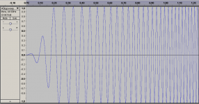
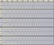
Attachment shows infading for the logsweep
KSTR said:Coming back to this, when I reduced order to 14 (16k sample lenght) I am able to use convolution, but get sort of garbage when I try to convolve the stimulus with the inverse. Of course still the stimulus .WAV has that data corruption problem which might explain things, at least in part.
When I generate my own stimulus and its inverse (pretty easy to do in eg Audition, except for the raised cosine stuff, which I ommited for this sanity check) everything is fine, I get a pretty clean dirac (left part of it) with just the chosen spectrum of the stimulus.
Yes there was a bug with the InFade and OutFade for the LogSweep. Also a sync bug, when writing wave-files
It was a good idea to write the wavefiles for inspection
Hope this is solved now
http://www.holmacoustics.com/downloads/HOLMImpulse/ChangeLog.txt
Version 1.1.6.4 (2009-06-22)
Features/Changes:
* LogSweep - Variable Infade & Outfade
Bugfixes:
* LogSweep - Infade & Outfade
* Save signal as wave file (Syncing file-buffer)
I also find it interesting to play around with infade+outfade values
and see the inverse correlator.
I checked to see if the inverse correlator was correct. And I got a pure dirac at sample = 0 when folding the two signals. How do you fold the two wave files?
Attachment shows infading for the logsweep
Attachments
Another release - I try again...
In Version 1.1.6.4 there was an update bug, when adjusting the logsweep in/out fading
It's solved now in version 1.1.6.6
fold -> convolve in my above post... It was a little danish - I better go to sleep now
Attachment show logsweep infading wavelengths 0-4
starting at 10 Hz @ 44.1 kHz
In Version 1.1.6.4 there was an update bug, when adjusting the logsweep in/out fading
It's solved now in version 1.1.6.6
fold -> convolve in my above post... It was a little danish - I better go to sleep now
Attachment show logsweep infading wavelengths 0-4
starting at 10 Hz @ 44.1 kHz
Attachments
>> I checked to see if the inverse correlator was correct.
>> And I got a pure dirac at sample = 0 when folding the two signals.
>> How do you fold the two wave files?
I loaded the inverse as convolution kernel into Audition and then had the stimulus (which was corrupted) processed. The stimulus was padded with its own original length with zeros at the beginning and end, to have room for processing (Audition doesn't lengthen the result according to the kernel length).
I also "forgot" (on purpose) to mention that the imported inverse was wrong in time, not reversed. That was the essential problem it just couldn't work at all.
-----:-----
In the meantime, while you were working hard, I was working on self-education, too, and made myself a 5 second (@44.1k) stimulus-inverse pair, bandlimited from ~5Hz to ~19.5kHz which gives the perfect corresponding IR when folded. This was done in two steps, at first I applied a 200ms cos fade-in, made the inverse from it and then run both through a nice linphase 19.5kHz brickwall filter kernel I had made yersterday for some other investigation. This gave a nice corresponding fade-out. A lot of manual trimming etc was necessary at various steps, though. And Audition's kernel size limit is some 200k samples, so longer kernels don't work unless one handles partitioning manually. That's why I appreciiate your software very much, even more than I did already!
Next educational step is to find out how a proper HF attenuation can be implemented, to lessen the potential risk of burning tweeters or clipping amps (I own active near-field monitors where the HF-amp has only half of the headroom of the LF-section).
I'll check the new features(/fixes and report back. This software is getter better and better by the day, don't know where that is going to lead to...
Er, would you care to explain the option fields for the chirp and MLS signals on occasion?
- Klaus
EDIT: typos
Re: Another release - I try again...
Sleep well, dude!
- Klaus
it's english too, "to convolve" is latin, essentially.askbojesen said:fold -> convolve in my above post... It was a little danish - I better go to sleep now
Sleep well, dude!
- Klaus
KSTR said:Er, would you care to explain the option fields for the chirp and MLS signals on occasion?
Yes, please do! We'd like to know what they do.
Software is getting better and better. I have found it very useful so far. Not sure why, but I find it much easier to get good, consistant results with HOLMImpulse than any other software like it. Thanks!
Takket så meget - as they say!
- Home
- Design & Build
- Software Tools
- HOLMImpulse: Measuring Frequency & Impulse Response