8.5m sounds more realistic to be, but is small enough it might not matter. You can look at the Vbe plot and look at where Vbe becomes resistive, because the emitter resistance takes over and it becomes a straight line. You can calculate the resistance from that line. But this can be due to both Re and Rb, so more information is helpful. Rc can be adjusted when doing Vcesat curves.
Maestro keantoken,
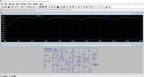
Im working on this circuit using your spice directives, copy pasted from ampsim2.asc I think. The squarewave swings on + rail only. I wanted to see how the negative swing looks like because clipping behaviour is assymetrical. Can you please check it out if I miss something in the directives?
Thank you!
Albert
Attachments
It looks like you deleted one of the square sources and some directives. They are not meant to be broken up and used separately, but all together in series, using directives to turn them on and off. Maybe you got an old version. This is what I'm currently using.
Also you OLG probe placement is wrong. It needs to have the output stage on one side and the load and feedback point on the other side.
Also you OLG probe placement is wrong. It needs to have the output stage on one side and the load and feedback point on the other side.
Attachments
Last edited:
")
It looks like you deleted one of the square sources and some directives. They are not meant to be broken up and used separately, but all together in series, using directives to turn them on and off. Maybe you got an old version. This is what I'm currently using.
Also you OLG probe placement is wrong. It needs to have the output stage on one side and the load and feedback point on the other side.
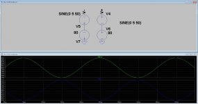
I'm puzzled, I got triangle waves. Did I connect it alright? I had it set to output squarewave.
Attachments
Simple Bridge Rectifier LTSpice Model
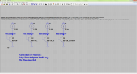
Hi. I wonder if this is the right place to add this. I created a basic bridge rectifier ltspice model. I'm sick of creating the same thing every time I start a power supply circuit, or test certain things. So for anyone who wants it, put the BR.asy into your sym folder (I put my way down into sym\Misc\Custom). Put the BR.sub into sub.
You can edit the .sub to change the diode if you want. This model uses D - the generic diode.
Attachments
SPICE model of BD139-BD140
I recently ran a simulation of a "Bailey" 30W using these as driver and pre-driver transistors. SImualtions showed worse distortion than expected. CHecked the models and found that they are still the old ones which lineup reported 10 years ago as not being suitable.
Just started making a model of the BD140. What I can say is that the particular device I measured had a forward gain of 220, reverse 12, VAF of 86, VAR 31 compared with the spice file I had which gives VAF=20, BF=335, so clearly not ideal.
Without optimising the new model (still to be completed) the distortion in the amplifiers reduced by a factor of 2, more in line with expectations.
I do not recall the origin of the model I am using but one well known company once produced models based on data sheet parameters which is pessimistic particularly for VAF as the model appears to describe the leakage current (and the SPICE model treats this linearly: in practice the leakage current is due to an increasing pre-avalanche breakdown field and rises sharply near BVceo. At lower Vce's the output current is much flatter with voltage.
Last edited:
I haven't seen pessimistic models so much as models that were just plain garbage, with parameters which made no sense and that didn't resemble the intended transistor very well.
Bob Cordell has handmade models of the BD140/139 here:
CordellAudio.com - SPICE Models
Bob Cordell has handmade models of the BD140/139 here:
CordellAudio.com - SPICE Models
Thanks for the link. But there are already apparent differences. The Bob Cordell BD140 model gives a lower gain and higher VAF than I have measured!
This just shows that individual transistor parameters can vary significantly from the models. And one SPICE model will not cover the range of devices possible. However, for the particular parameters VAF and hfe the product tends to be (almost) constant. Bob's figures are 113 x 140=15820 while my measured data is 220 and 86 =18920. EIther would work better than the original model.
This just shows that individual transistor parameters can vary significantly from the models. And one SPICE model will not cover the range of devices possible. However, for the particular parameters VAF and hfe the product tends to be (almost) constant. Bob's figures are 113 x 140=15820 while my measured data is 220 and 86 =18920. EIther would work better than the original model.
Yes, there is a lot of variation, especially in Vaf. It seems most common transistors these days have very low Vaf, which is a pain. Bob didn't mention which manufacturers his parts came from which is also an ambiguity when you have parts like the BD140/139 which can be totally different depending on who makes them.
Bob Cordell's site has his BD139/BD140 model.
I suspect you have the MODPEX file in your simulator. That is quite useless IMHO. FOr example IS=somethingE-9, should be E-13 to -14; NF 0.85 nearly all Si transistors have NF=1.0something.
I challenged ON Semi on this. They said their models are to datasheet spec. Well, no-one wants absolute limiting specs, but TYPICAL results for TYPICAL performance!
Don't think they listened.
And ST's SPICE model for BD139 refers to a completely different transistor (when I looked).
I need to simulatie temperature behavior, but it has to start after 500 mseconds. Now it starts right away and I can not see behavior.
thanks
Kees I think you can do a PWL source and use that as the {temp} variable.
Like PWL 0 25 500m 25 1 40 named T1 then .param temp {T1}.
Haven't tried it but should work.
Jan
Hi Gertjan
Thanks, for that, I have also discover that no use of skip initial operation point and start external voltages on 0 volts do give a good start, using one of them I see it does slowly setup after start.
I have done a sweep, but I think it does temperature sweep all the parts, including the regulator transistors, servo opamp, and that give a wrong picture of what is going on, normally al these part get not so hot.
I did want to see what happens with idle current runaway, the servo does take care of that and keeping also bias constant into the circlotron.
regards
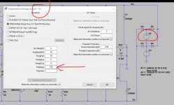
I did want ripple on the supply.
I have put a sinus signal in the supply for sim, is this right? I need to do 100 hz afcourse, but for the idea.
thanks.
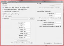
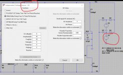
Ripple isn't sinusoidal. If you want to simulate ripple then try setting each rail like this (first image) or use a 'real' AC voltage source and rectifier.
Attachments
- Home
- Design & Build
- Software Tools
- Spice simulation