I just got a new place to live and thought it would also be a great opportunity to do some room treatment before I move in.
My idea is to cover the front an back wall in wood panels like this one here:
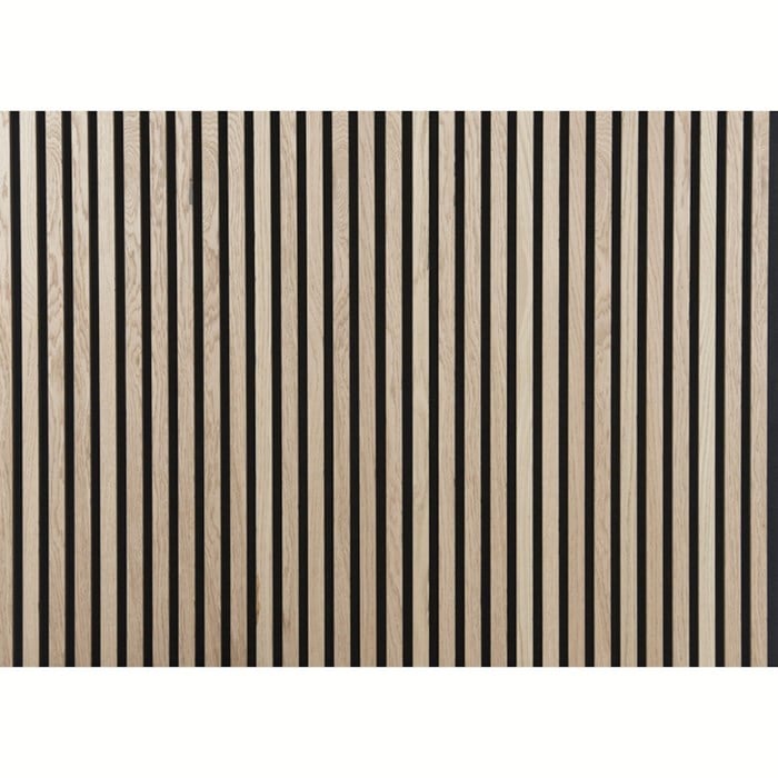
The front wall would be made with the wood on an acoustic fabric and act mostly as a diffuser and just giving a symmetrical look. The back wall would have the same wood and acoustic fabric, but here I plan to put 50-70mm of rockwool behind the wool wall.
The question is: I can imagine that the spacing between the wood strips would have an effect on what frequencies is reflected or maybe diffused and what frequencies that are passing through to be dampened by the rockwool. How do I find the correct spacing between the strips?
I have looked at some measurements of the store bought panels and they seem to have a fairly flat response in the mid to high frequency area, and i would expect that I can extend this to lower frequencies by adding the rockwool.
My idea is to cover the front an back wall in wood panels like this one here:
The front wall would be made with the wood on an acoustic fabric and act mostly as a diffuser and just giving a symmetrical look. The back wall would have the same wood and acoustic fabric, but here I plan to put 50-70mm of rockwool behind the wool wall.
The question is: I can imagine that the spacing between the wood strips would have an effect on what frequencies is reflected or maybe diffused and what frequencies that are passing through to be dampened by the rockwool. How do I find the correct spacing between the strips?
I have looked at some measurements of the store bought panels and they seem to have a fairly flat response in the mid to high frequency area, and i would expect that I can extend this to lower frequencies by adding the rockwool.
You could consider changing the width of the wood rods in irregular patterns. That would improve scattering of the reflected sound. Or build some kind of quadratic diffusor into it, would even be better. But combining the absorber with the wood rods alone will work well already.
I came across a link on a Swedish forum from poster Grahnbarr which should be of interest: https://users.aalto.fi/~ktlokki/Publs/p62_2018.pdf
In short; lesser open area percentage will mean more reflection of mids and treble (usually = positive) while at the same time increase of low frequency absorbtion (usually = positive). Decreased open area has more significance than insulation behind slats, within "reasonable thicknesses". Note: Going on the pictures from the test measurements, these are from a closed boxed filled with absorbtion and with slats on top. Personally, I would go for open area lower than 18%, around 5-10% or so, to avoid too much absorbtion of lower mids and above.
In short; lesser open area percentage will mean more reflection of mids and treble (usually = positive) while at the same time increase of low frequency absorbtion (usually = positive). Decreased open area has more significance than insulation behind slats, within "reasonable thicknesses". Note: Going on the pictures from the test measurements, these are from a closed boxed filled with absorbtion and with slats on top. Personally, I would go for open area lower than 18%, around 5-10% or so, to avoid too much absorbtion of lower mids and above.
Last edited:
Thanks for sharing the link. Very interesting paper! I might consider to try such an absorber diffusor combo.I came across a link on a Swedish forum from poster Grahnbarr which should be of interest: https://users.aalto.fi/~ktlokki/Publs/p62_2018.pdf
@Colakurt: Depends on the width of the slats, -what will the open area be? Also thickness of slats as well as gas flow resistivity of the insulation behind and the thickness of it plays a role.
Enclosed is a similar paper from an investigation of slat absorbers from KTH in Stockholm (Royal Institute of Technology). The setup follows international standards with about 10 m² of slat absorber in an echo chamber. The paper is in Swedish but Colakurt as a Dane might be able to read it. For others; the diagram "B.1.1.2 Glasull som porös dämpning" (B1.1.2 Glass wool as porous damping) towards the end is quite easy to understand. Translation of the setup / test: Slat = 70 mm wide x 16 mm thick, common wall insulation with density 14,5 kg/m³, 70 mm thick directly behind the slats and concrete directly behind insulation.
The setup forms a closed air tight box behind the slats. In other words a Helmholtz absorber is formed tuned to max absorbtion at different frequencies depending on the width of the gap between slats = open area. Gap width is varied between 1 to 16 mm versus the slat width of 70 mm.
The diagram above is a similar test with but with rock wool, density 70 kg / m³, 50 mm thick and with 20 mm air gap between wool and concrete. ("B.1.1.1 Stenull som porös dämpning")
As can be seen; a decreased percentage of open area increases absorbtion towards lower frequencies and lowers absorbtion for higher frequencies = more reflection and / or diffusion if the slat gets an added piece of wood on top of the slat. The addition less wide than the slat itself.
So ... what frequncy range is of most interest to absorb efficiently? Check the gap width and calculate the open area versus slat width 70 mm if you wish to use another slat width.
Attachments
Last edited:
I am a little surprised with only 2 views of the pdf so far. The diagrams are actually very useful if one is considering low frequency absorbtion with narrow depth whie at the same time not "over absorbing" in the mids and treble. (The diagrams are after page 39, 2 pages on, after the literature list / references.
Well, if I posted research papers in Dutch, I fear the same would happen. And to be true, combined slat resonators/porous absorbers/diffusors really aren't that new. I think I've been calculating on them way back in university around 1990. But it is a fine paper as it is, I added it to my collection.
You are quite right, unless papers are in English (or German / French) they get little attention on internet. A good thing about the Swedish one is that reported results in diagrams and texts are actually measured ones (not calculated) from an echo chamber and done according to standards with absorber size about 10 m². Diagrams are often easy to understand even if the text itself is in a foreign language.
Happy to notice you know what you are talking about. And you are right about the value of measurements. But I didn't refer to my own calculations 
I was lazy and grabbed my copy of FA Everest just to find out Mankovsky did measurements on slat absorbers and published them in 1971 No references to him in the Swedish report though...
I was lazy and grabbed my copy of FA Everest just to find out Mankovsky did measurements on slat absorbers and published them in 1971
No references to him in the Swedish report though...I came across a link on a Swedish forum from poster Grahnbarr which should be of interest: https://users.aalto.fi/~ktlokki/Publs/p62_2018.pdf
In short; lesser open area percentage will mean more reflection of mids and treble (usually = positive) while at the same time increase of low frequency absorbtion (usually = positive). Decreased open area has more significance than insulation behind slats, within "reasonable thicknesses". Note: Going on the pictures from the test measurements, these are from a closed boxed filled with absorbtion and with slats on top. Personally, I would go for open area lower than 18%, around 5-10% or so, to avoid too much absorbtion of lower mids and above.
Very useful. After doing and continuing to do extensive acoustic treatment research while building three or four types currently. I never came across those pages. There are 1001 great looking designs out there, but dimensions for many are illusive.
For instance some of the dual purpose diffusion /absorption and 90 degree bass traps at gika are a cinch to build. If I could only get precise spec paper to work from
I'm familiar with the calculators but I don't posses mics or sound analyzing equipment for testing. Already tried and tested / proven would offer some peace of mind.
I have a 7' by 7' opening in my listening room ceiling that I need to address. I was thinking of a slat diffuser just like figure 4. Too bad for me that the paper was limited in scope to absorption. I'd love to see a study on the diffusive properties of that pattern. Anyway, at least now I have a pattern. My thanks and appreciation to the authors!
Maybe I'd flip the sequence so it looks more like a QRD and figure on 7 number sequence in stead of 5.
Maybe I'd flip the sequence so it looks more like a QRD and figure on 7 number sequence in stead of 5.
Last edited:
- Home
- General Interest
- Room Acoustics & Mods
- DIY Acoustic wood absorber