No acceleration feedback is for a subwoofer, also to use transconductance amplifiers.
When you try out LP filter and HP filter for the circuit, you can place the absorber in a room with lots of reverberation and play notes at the resonant frequency, then measure the reverberation time. You can use waterfall diagram in rew. You shall aim for as high feedback level as possible without the absorber giving to much noise itself. That can either be hf resonance (high pitch tone) or lf resonance (hum). It dependson microphone placement, element parameters, phase margine of the filters used.
When you try out LP filter and HP filter for the circuit, you can place the absorber in a room with lots of reverberation and play notes at the resonant frequency, then measure the reverberation time. You can use waterfall diagram in rew. You shall aim for as high feedback level as possible without the absorber giving to much noise itself. That can either be hf resonance (high pitch tone) or lf resonance (hum). It dependson microphone placement, element parameters, phase margine of the filters used.
Good Idea to use a transconductance amplifier. It will tend to cancel thé inductance of thé voice coil, resulting in more phase margin in HF. Do you have a schematic to share of tour transconductance amplifier?
The Idea of accélération feedback was to lower thé frequency opération of thé absorber without adding mass. Do In triéd to implementing it by attaching thé electret mic to thé coil... I did Not obtained satisfactory résults. One could also use a voigt bridge to measure cône velocity ans dérive that to obtain acceleration... In the end I added PVA glue to thé cône and obtained tangible résults.
Next thing I will try IS increasing thé absorbtion capacity of thé sealed box itself. Instead of having a cubic box, I'll try to have a 'tubish' box, I think this should increase particule velocity ans thus increase dissipation in thé rockwool.
What Do you think?
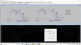
transconductance vs voltage amplifier
Did some time ago a quick simulation comparing transconductance vs voltage amplifier.
Simulation confirms that with a transconductance amplifier
* we get more cancellation around fsb (78Hz)
* we get better phase margin: bump @ 1khz is smaller
Unfortunately, due to time constraints, didn't tried transconductance amplifier yet ...
Attachments
some measurements
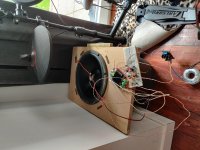
#1 : active bass trap prototype with feedback loop voltage amplifier and first order low pass filter with phase lag compensation. Cone treated with PVA glue.
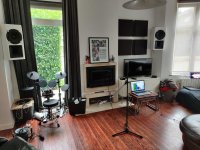
# 2 : please notice windows acting already as bass traps. The ceiling is made of drywall also acting as bass trap...
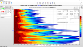
# 3 : measurement with bass trop off
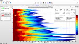
# 4: measurement with bass trap on
I did measurements when prototype placed in several corners in the room, #4 is the best I could get, it is when it is placed in the corner next to the drums.
#3 & #4 demonstrates a measurable effect") .
.
For my room I think I will build at least 3 of them, I will place those in the corners above the speakers and one next to the drums.
Any thoughts?
#1 : active bass trap prototype with feedback loop voltage amplifier and first order low pass filter with phase lag compensation. Cone treated with PVA glue.
# 2 : please notice windows acting already as bass traps. The ceiling is made of drywall also acting as bass trap...
# 3 : measurement with bass trop off
# 4: measurement with bass trap on
I did measurements when prototype placed in several corners in the room, #4 is the best I could get, it is when it is placed in the corner next to the drums.
#3 & #4 demonstrates a measurable effect
.For my room I think I will build at least 3 of them, I will place those in the corners above the speakers and one next to the drums.
Any thoughts?