Now, that would be a neat product for the diyaudio store.....
I still like the idea of using polycarbonate, for a transparent diffusor. The 'boxes' could be 2" slices of square plastic stock (or molded that way?), just glue a bunch of them together in a grid to the size needed, stick on a backing board and cover with the hole-patterned sheet. An evening's sticky effort in construction.
I still like the idea of using polycarbonate, for a transparent diffusor. The 'boxes' could be 2" slices of square plastic stock (or molded that way?), just glue a bunch of them together in a grid to the size needed, stick on a backing board and cover with the hole-patterned sheet. An evening's sticky effort in construction.
Source of rectangular tubing
Guess I should probably look and see what the actual dimension of "D" needs to be before finding tubing though......
Guess I should probably look and see what the actual dimension of "D" needs to be before finding tubing though......
5x5 means about 1350 Hz for Fc, though, (10" wavelength), and 1/2" pocket depth.
Just now trying to read and figure how to calculate that.... is that in the 'Supplemental Information"?
EDIT: should have read further before posting, sorry.... when I went to look at things, I was copying out plots to look at and made it a post too early. Figure 5 in the article posted about by Pano shows technique for some pretty effective bandwidth widening of the metasurface diffusor. Certainly complicates things. Anyway, I'll leave the below just-in-case it has relevance to the discussion
------------------------
Here looks to be a bug in the ointment: "The results demonstrate that the MSD has normalized diffusion coefficients comparable with the conventional SD in the vicinity of the center frequency"
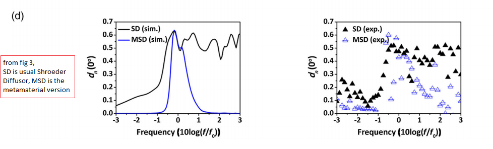 The bandwidth doesn't look very wide, compared to the usual Shroeder diffusor or evolutionary-optimized step diffusor. Unless I'm reading this wrong.
For instance, the 'depot' diffusor covers (in modeling at least, who knows? in measurements...) from about 500 to 8kHz --
------------------------
Here looks to be a bug in the ointment: "The results demonstrate that the MSD has normalized diffusion coefficients comparable with the conventional SD in the vicinity of the center frequency"
For instance, the 'depot' diffusor covers (in modeling at least, who knows? in measurements...) from about 500 to 8kHz --
Attachments

Last edited:
Yes, I saw that and it worried me. But it made me wonder if that's the reason to have multiple frequency points. What is the bandwidth if each block in a normal skyline diffuser? Or the slots of the other types? Are they more broadband?
EDIT. Their graph does show the normal SD to have much better bandwidth. But there were some solutions to that, will have a look.
EDIT. Their graph does show the normal SD to have much better bandwidth. But there were some solutions to that, will have a look.

One of the guys is at NC State, the others are at Nanjing.
That is where he is now. That often means he was a graduate student who did significant work and has now moved on.
The work strikes me as a first step. It points out the ability to use a phase wiggling device in a matrix to produce diffusion.
The device is easy to build with a simple 3 axis CNC router. I gave a copy of the paper to one of my guys to get his take on it. Should be easy enough to make one for next weekend.
I expect that to get one working down to 125 hertz will more realistically make it a wall panel. So I see it as still a multiple depth device with high frequency cells in front of the lower frequency ones. I also expect Fiberglas in the cells to broaden frequency bandwidth and lower Fc.
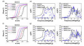
Looks like their particular BMSD examples cover about an octave.
BMSD will be more tedious to build, with internal cell widths (D) that vary as D=λ/2. It appears that cell center spacing is kept constant, so wall thickness between the cells must be varied to create the different D's. Eliminates Bill's neat box construction method unless you can match four appropriate λ/2 side lengths that add to make a square.
Keep in mind the cell width to depth ratio is 10:1. With a 14 x 14 unit grid as used in their BMSD example, overall size may be a factor at even medium frequencies. Using Daniel's 1350Hz as a low f would yield a 6' square. Their 343Hz 5cm deep MSD 7x7 unit example would be big, 3.5m per side with 50 cm x 50cm cells.
How are you guys getting the "depth ratio is 10:1"?
My (apparently wrong) interpretation was that they were setting the width based on the lowest frequency to be handled (somehow....) and selecting actual resonant/rapid phase-change frequency by the size of the square hole on the surface?
My (apparently wrong) interpretation was that they were setting the width based on the lowest frequency to be handled (somehow....) and selecting actual resonant/rapid phase-change frequency by the size of the square hole on the surface?
Are you seeing the "lamba/2" in the diagrams to be the cell width? I saw those as the maximum depth of the basic Shroeder well they are comparing against.
Ah, nevermind, found it: "The width and thickness of the unit are D ¼ λ0=2 and λ0=20"... I don't think those are magic values, though, just a workable ratio they picked
Ah, nevermind, found it: "The width and thickness of the unit are D ¼ λ0=2 and λ0=20"... I don't think those are magic values, though, just a workable ratio they picked
Last edited:
from page 3 of the 1st pdf referenced in the original post:
"metastructure units shown in the inset of Fig.1(c). The width and thickness of the unit are D=λ/2 and λ=20, respectively. In this study, the neck width of the cavity w is the only tunable parameter for controlling the phase shift of the metastructure unit"
λ indicating center frequency wavelength, I don't know how to do subscripts here. Coincidentally (or not) the same as the max depth of the SD wells.
Another fabrication idea: This could be made from side-to-side strips of styrofoam sheet, with each of the holes straddling two strips. This would allow a hot-wire cutter to cut the square holes into the sides of the strips, as channels.
After all of the individual styrofoam strips are made, they would be glued together to complete the functional core of the diffusor.
After all of the individual styrofoam strips are made, they would be glued together to complete the functional core of the diffusor.
- Status
- This old topic is closed. If you want to reopen this topic, contact a moderator using the "Report Post" button.
- Home
- General Interest
- Room Acoustics & Mods
- A very thin Schroeder diffusor